Quick install, Instructions, Mini megapac “quick install” instructions – Vicor Mini MegaPAC AC-DC Switcher User Manual
Page 10
UG:110
vicorpower.com
Applications Engineering: 800 927.9474
Page 10
Mini MegaPAC “Quick Install” Instructions
(For Mechanical Drawing, see Page 13)
Mounting the Mini MegaPAC
n
The Mini MegaPAC can be mounted on any of four sides.
n
Use #8-32 or 4 mm mounting screws. Maximum penetration should
not exceed 0.15” (3,8 mm).
n
Maintain 2” (5,1 cm) clearance at either end for airflow.
n
Maximum allowable torque is 20 lb-in.
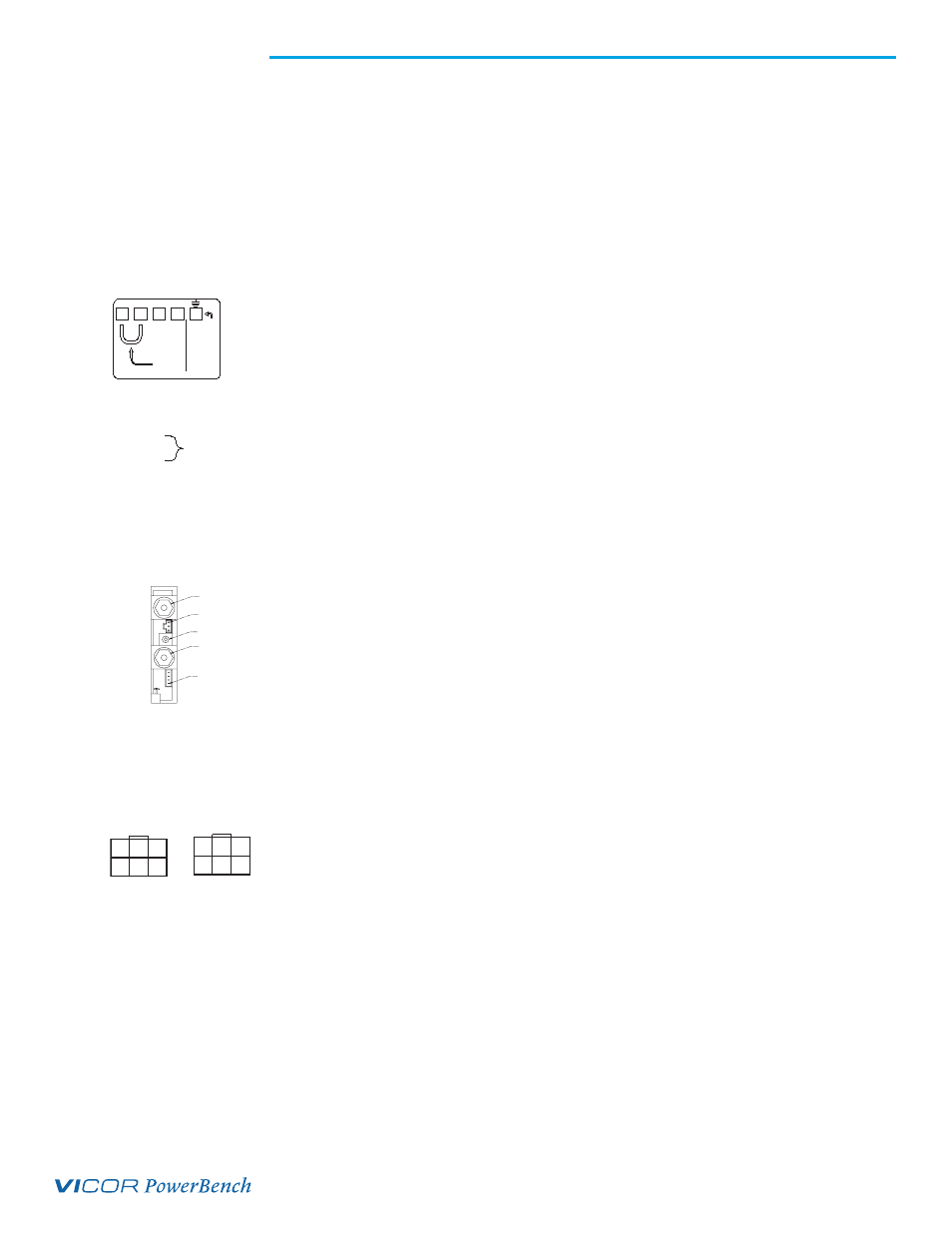
Input Connections
Input Power J9
n
Input AC power is applied to terminal block J9 using a pressure screw terminal.
n
Maximum torque is 10 lb-in.
n
When operating from 230 Vac, verify the strapping wire (provided) has been removed
from J9-4 and J9-5. Operation from 230 Vac with the strapping wire installed will
damage the power supply.
n
When operating from 115 Vac, verify the strapping wire (provided) has been installed
between J9-4 and J9-5.
n
A fuse or circuit breaker is reequired in the input line for safety reasons.
n
Use a maximum wire size of 10 AWG with soldered terminals.
Output Connections
Power Connections
Installing ring lugs and/or bus bars on output studs:
n
The upper stud is Positive and the lower stud is the Return.
n
Remove outer nut. Do not remove or loosen inner nut.
n
Place ring lug over output stud.
n
Replace and tighten outer nut to a maximum torque of 45 lb-in.
Do Not Over-Tighten Nuts.
n
Verify all output nuts are properly installed before turning on supply.
Installing power connectors on DualPACs (J1A and J1B):
n
Use Molex mating receptacle #39-01-2060 with #39-00-0039 terminals provided.
n
Pins 1 and 4 are Positive, while pins 2 and 5 are the Return.
n
Attach terminals to 18-24 AWG stranded wire using Molex tool #11-01-0197.
Sense Connections
Note: Newer power supplies have a new feature called Autosense. If Remote Sense connections are
not made or needed, no Local Sense selection is necessary - simply hook up the output and
the unit will automatically operate in Local Sense. If Remote Sense connections are made,
the unit will operate in a Remote Sense mode. Remote Sense terminals should be terminated to
their respective output i.e. - RS to - Output and + RS to + Output.
See page 13 for more information on Autosense.
For units without Autosense, sense connections must always be made. Not connecting Sense
lines to their respective outputs can cause failure to the unit.
115V OPERATION
JUMPER FOR
J9-5 120 VAC
J9-4 120 VAC
J9-3 AC NEUTRAL
J9-2 AC HOT
J9-1 EARTH GROUND
J9 INPUT CONNECTIONS
L2
S2
L1/N
HERE.
EARTH
JUMPER
230 VAC
AS IS
-OR-
115 VAC
WITH S1-S2
DO NOT
RUN W/O
GROUND
S1
J2-PIN1
J3-PIN1
0UTPUT ADJUST
+ V0UT
- VOUT
MODUPAC
6 -REMOTE SENSE
3 +REMOTE SENSE
2 & 5 -V OUT
1 & 4 +V OUT
PIN
J1B
+
4
6
-
5
+
+RS -
-RS
3 2 1
J1A
3 2 1
4
6
+RS
-RS
+
+
-
5
-
Input Panel Connectors
Single Output ModuPAC
DualPAC Output Connector