Vertical high output, Electrical, General precautions – Titus VHC IOM User Manual
Page 2
VERTICAL HIGH OUTPUT
VHC-IOM-00 01-19-09
INSTALLATION AND
MAINTENANCE INSTRUCTIONS
5
f
o
2
e
g
a
P
4.
ELECTRICAL
4.1
All electrical connections are to be made in accordance with the National Electric
Code, state and local codes, bylaws, ordinances or the authority having jurisdiction.
Make all electrical connections inside the internal electric junction box by carefully
following the wiring diagram.
4.2
Electrical wiring diagram is located inside the unit’s enclosure. Adhere strictly to it in
order to avoid damage and/or personal injury.
4.3
When the thermostat and fan switch are field supplied, the following are the minimum
electrical ratings:
- Thermostat (valve load) = 0.1A @ 115V
(0.05A @ 230V)
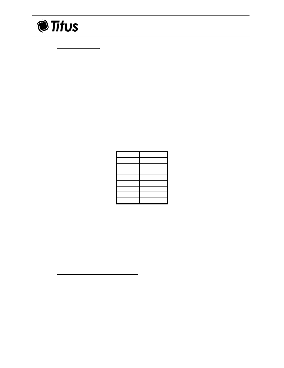
- Fan Motor(s) @ full load amps, FLA (@115V):
SIZE
FLA (Amps)
06
3.5
08
3.5
10
3.7
12
4.0
14*
3.5
16*
3.5
18*
3.5
20*
4.0
*Note: Units are equipped with two (2) motors; full load amperage listed is per motor.
4.4
Where electric heating is provided with the unit (optional), an external HEAT/COOL
changeover switch has to be installed – normally wall mounted together with the fan
speed selector switch. At minimum, this switch should be rated: 10A @ 115V (5A @
230V).
4.5
Follow the wiring diagram for correct installation.
5.
GENERAL PRECAUTIONS
After completing the installation, recheck the following:
5.1
The drain pans, fans and motors are clean of all foreign material.
5.2
All electric wiring is properly routed, secure and capped.
5.3
The filter is clean and secured in its position.