End fabrication, Diffuser assembly instructions – Titus ML IOM User Manual
Page 2
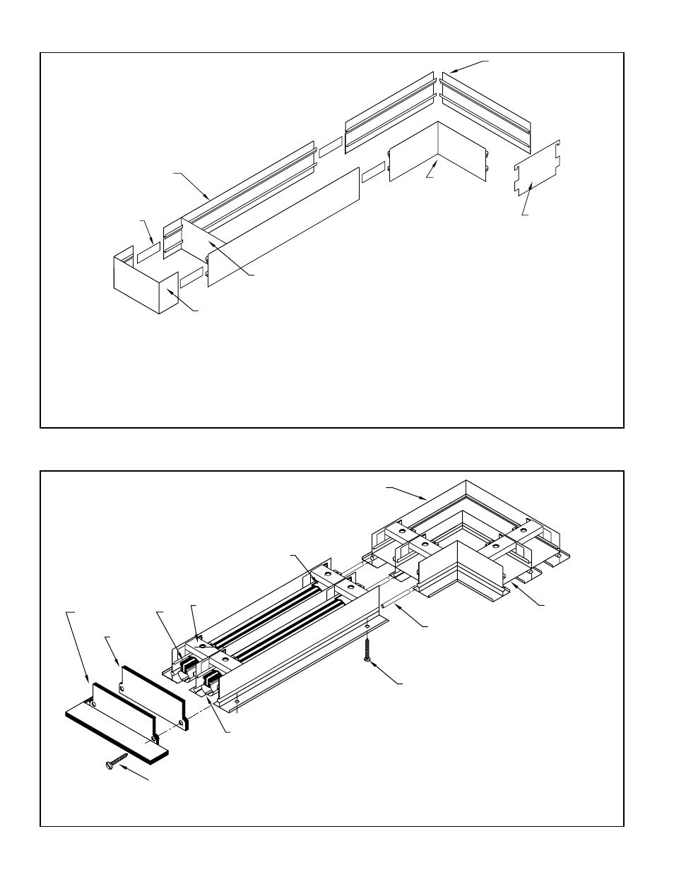
End Fabrication
(Factory Welded)
End Frame
Strip
Alignment
Rail
Side
Assembled
Gauge
Temporary
Corner
Field
Temporary
Gauge
Corner
Field Assembled
Diffuser Assembly Instructions
#8 x 1 1/4 Oval Head Screw
(Border Type 1A only)
(Welded)
Factory
Spacer
#6 x 1/2 SMS
Optional
End Cap
End Border
Optional
Blade
Bar
Support
Controller
Pattern
Spring Clip
Alignment
Pins
Corner
Mitered
Blank-Offs
Optional
1. Determine size of duct opening. Duct width depends upon model,
frame & border type and number of slot. See Duct Dimensions D’
table (Page 7). Duct length is as ordered.
2. First install end frames and field assembled corner pieces in ceiling
opening. Then cut side rails to length and install. Use alignment strips
furnished with frame parts to connect side rails, corners and end
frames to each other.
Note: When end borders are not to be used with diffuser, mounting
frame ends are not furnished.
3. Use removable gauges furnished with frame parts to ensure
proper fit of diffuser into mounting frame. Gauges snap into place
between side rails as shown above. If mounting frame is to be plas-
tered into place, use wood blocks to stiffen side rails and maintain
correct inside dimensions.
1. Assemble diffuser with alignment pins as shown above. End
borders or caps, where ordered, are attached at factory.
2. Install diffuser in ceiling. See Hanger Bracket Mounting
Instructions (Page 4).
Note: Mounting frame is used only on
Frame & Border Types 3, 4, 6, 7A, 7B, 11.
2