Installation, Materials required, Installation checklist – Regency Horizon HZI540PB Large Gas Insert User Manual
Page 10: Minimum fireplace dimensions
10
L540PB-2 / HZI540PB-2 Direct Vent Gas Insert
INSTALLATION
MATERIALS REQUIRED
Electrical power supply (120V) for the fan to operate. Plug the 3 wire cord
into a suitable receptacle. Do not cut the ground terminal off under any
circumstances. When connected with 120 volts, the appliance must be
electrically grounded in accordance with local codes, current version of CSA
C22.1 (in Canada) or in the absence of local codes, with the National Electrical
Code ANSI/NFPA 70-1987.
INSTALLATION
CHECKLIST
Before installing vent system ensure that the damper plate is open and secure
to prevent the damper plate from falling down and crushing the liner.
The Regency Gas Insert is installed as listed.
1) Check all clearances to combustibles, (Refer to sections "Minimum
Fireplace Dimensions and Clearances to Combustibles)
2) Make the gas connection. (Refer to section "Gas Connection") Gas
connection is on the left side of the appliance.
3) Install the two fl ue liners (intake and exhaust) to the sliding connector
plate. (Refer to section "Flue Liner Installation.")
4) Slide the unit half way into the fi replace.
5) Pull the vent connector plate through the brackets and fasten to the front
plate. Refer to section "Flue Liner Installation.")
6) Slide the unit fully into the fi replace. Level if necessary.
7) Test gas pressure (Refer to section "Gas Pipe Pressure Testing"). Check
aeration system (Refer to section "Gas Insert Aeration System").
8) Install standard and optional features. Refer to the following sections:
a. Brick Panels
b. Enamel Panels
c. Log Set
d. Glass Crystals
e. Spa stones
f
1
. Low Profi le Faceplate with Optional Screen
f
2
. Full Screen Door
g. Remote Control
9) Code remote control. See Remote Control Instruction Manual.
10) Final check: Before leaving this unit with the customer, the installer must
ensure that the appliance is fi ring correctly. This includes:
a) Clocking the appliance to ensure the correct fi ring rate.
b) Adjusting the primary air, if required, to ensure that the fl ame does
not carbon. See "Gas Insert Aeration System" section.
c) Ensuring that the appliance is venting correctly.
A
B
C
D
E
F
C
D
G
C
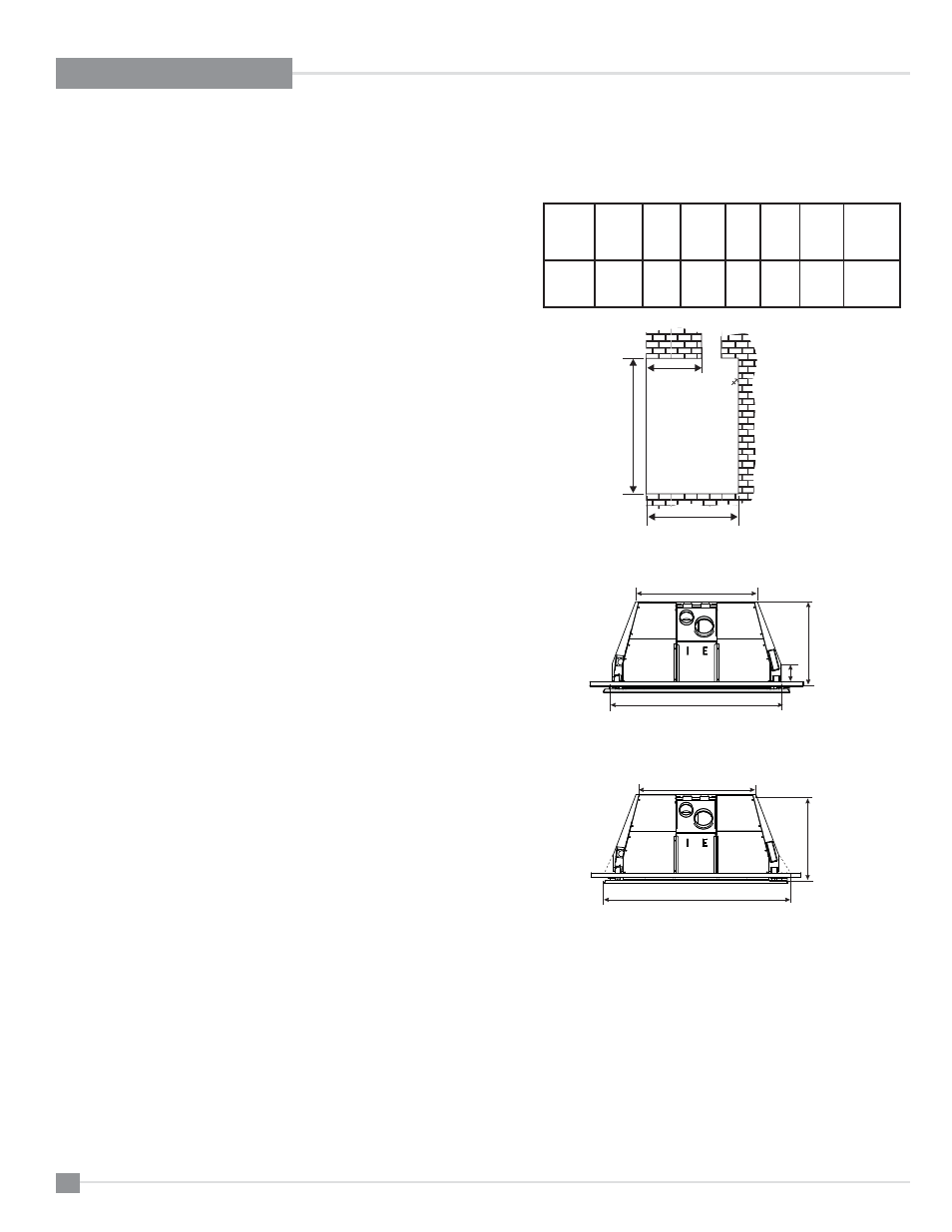
MINIMUM FIREPLACE
DIMENSIONS
The minimum fi replace clearances & dimensions for the Regency gas insert
are shown in the following diagrams:
Max
Lentil Bar
Depth
A
Height
B
Overall
Depth
C
Width
(rear)
D
Width
(front)*
E
Front
Depth
(prior to
taper)
F
Width
(front)*
G
Low
Profi le
Face-
plate
10
24"
17-1/4"
26"
36"
3-1/2"
38-11/16"
Side View
Top View
Top View