Electrical installation, Voltage inputs, Current inputs – SATEC EM920 Installation Manual User Manual
Page 14: Ground input, Typical installation, Form 9 wiring configurations, Figure 6: form 9 typical electrical installation, Table 1: wiring configuration
Chapter
8
Electrical Installation
Before installing, ensure that all incoming power sources are
shut OFF. Failure to observe this practice can result in serious
or even fatal injury and damage to equipment.
Voltage Inputs
There are 3 AC Y-connected voltage inputs of 207VAC (phase-to-phase) and neutral, via
socket meter blades.
The EM920 Power Supply Inputs are the same as the Voltages Inputs
Current Inputs
There are 4 current inputs up to 50A, connected to external CT’s via socket meter blades.
Ground Input
Make sure the EM920 socket is properly connected to ground
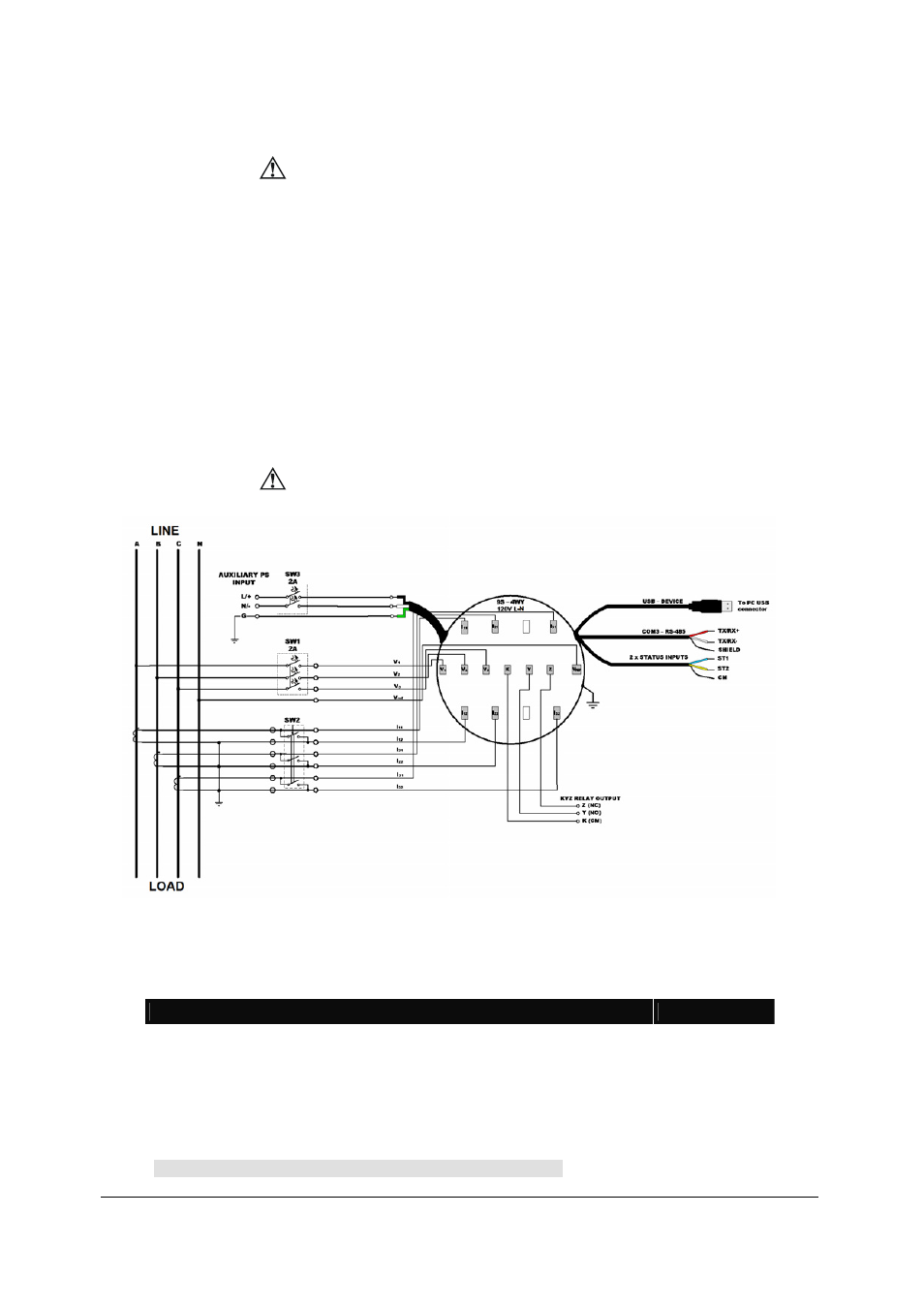
Typical Installation
Before installing, ensure that all incoming power sources are
shut OFF and are protected with a slow blow fuse of 2A (SW1
and SW3), and short the current inputs (SW2)
Figure 6: FORM 9 Typical Electrical Installation
FORM 9 Wiring Configurations
There are six wiring configurations shown in Figures 7, 8, 9, 10, 11, 12;
W i r i n g C o n f i g u r a t i o n
Wiring Setup
See Figure:
4-wire WYE 3-element using 3 CTs
4Ln3
4-wire WYE 3-element connection using 3 PTs, 3 CTs
4Ln3
4-wire 3-element delta using 3 CTs
4LL3
4-wire 3-element delta connection using 3 PTs, 3 CTs
4LL3
3-wire 2-element connection using 2 CTs
3OP3
11
3-wire 2-element connection using 2 PTs, 2 CTs
3OP3
12
Table 1: Wiring Configuration
See parameter setup instructions in the Operation Manual