Chapter 2 installation 16 – SATEC C191HM User Manual
Page 25
Chapter 2 Installation
16
9-PIN DB9 FEMALE CONNECTOR
POWERMETER
14
15
13
RS-232
RTS
CTS
8
7
RxD
TxD
SG
TxD
DTR
DSR
6
4
3
RxD
GND
5
2
c99-11015
IBM PC/COMPATIBLE
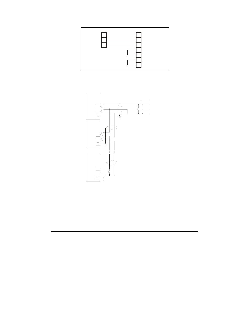
Figure 2-15 RS-232 Simple 3-Wire Computer Connection, 9-pin
Figure 2-16 RS-485 Multi-drop Computer Connection
NOTE:
Where an RS-232/RS-485 converter is used on a computer connection, R1 is not
applicable since it is built in to the converter.
Activity on the communications port lines is indicated via the TXD and RXD
LEDs, on the front panel and via the Status Information menu (see Chapter 6).
A full description of the communication protocols may be found in the C191HM
ASCII, Modbus and DNP3.0 Communications Manuals provided with your
c99-09035
+
+
+
-
-
-
C192PF8 POWER FACTOR CONTROLLERS
IBM PC /COMPATIBLE
or RS-2 32/RS-485 CONVERTER
RS-485
RxD
R1
#1
13
13
13
15
15
15
14
14
14
#2
R2
#32
TxD
TxD-
RxD-
Shi eld
Sh ield
R1, R2 = 200-500 Ohm,
0.5W
Shield