16_post02_4855e_boltpost_rev_03, Eagle rural mailboxes – 4855e – Salsbury Industries 4855E Eagle Rural Mailboxes Standard Mailbox Post User Manual
Page 16
SALSBURY INDUSTRIES
1010 East 62
nd
Street, Los Angeles, CA 90001-1598
Phone: 1-800-624-5269 Int’l Phone: 323-846-6700
Fax: 1-800-624-5299 Int’l Fax: 323-846-6800
www.mailboxes.com engineering
@
mailboxes.com
Installation instructions are provided as general guidelines. It is advised that a professional installer be consulted. Salsbury Industries assumes no product assembly or installation liability.
Copyright © 2011 Salsbury Industries. All rights reserved. (Rev. 03, 11/1/11)
Eagle Rural Mailboxes – 4855E
Bolt Mounted Mailbox Post Installation Instructions
U.S.P.S. APPROVED
Installing the Bolt Mounted Mailbox Post
When you install a curbside or rural mailbox, make sure that it is
easily accessible to the mail carrier. By regulation it should be 41” to
45” from the ground or street surface up to the inside floor of the
mailbox. The door should be set back 6” to 8” back from the front
face of the curb or the road edge. However, you should check with
your local postmaster to ensure that the mailbox is installed
according to local regulations.
To install the bolt mounted mailbox post, begin by digging a hole for
the concrete footing and then prepare the concrete. The top surface
of the footing should be about 12” by 18”. See the illustration for the
relative position of the rectangular footing to the post and mailbox.
The concrete should extend into the ground 24” or greater if your
local frost line is deeper. Installing the concrete below the frost line
will prevent movement during ground freezing and thawing. The
bottom of the hole for the concrete footing should be filled with a
depth of about 6” of gravel to promote drainage under the post. The
top of the footing should be sloped for water runoff.
When digging the hole for the footing, be careful to not puncture
water, sewer, or gas lines.
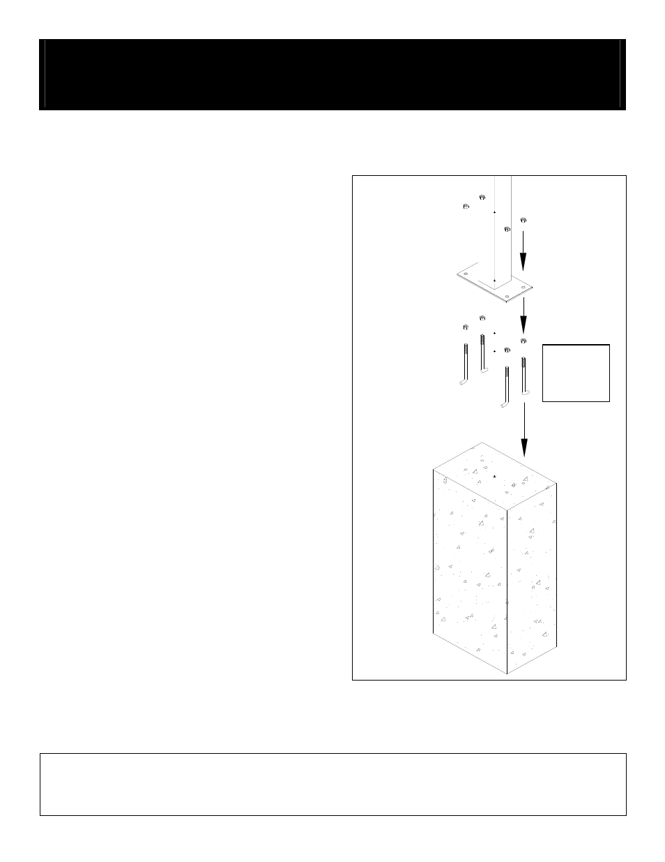
Hardware for attaching the pedestal to the concrete footing is not
included. J-bolts are shown in the illustration as an example. The
concrete footing should include reinforcing steel and four (4) 1/2”
anchor studs protruding at least 1” above the concrete surface.
Place the anchor studs in a 4” x 10” pattern in the concrete to align
with the holes in the pedestal base.
When the concrete has cured sufficiently, install four (4) leveling nuts
on the anchor studs. Set the pedestal on the leveling nuts with the
four (4) anchor studs protruding through the holes in the pedestal
base plate. Adjust the leveling nuts to square up the pedestal.
Install four (4) nuts and washers on the anchor studs and tighten
securely.
CONCRETE
ANCHORS
NOT
INCLUDED