Caution, 355c a v, Dimensions (in. / mm) – Bryant SERIES A 355CAV User Manual
Page 4
4
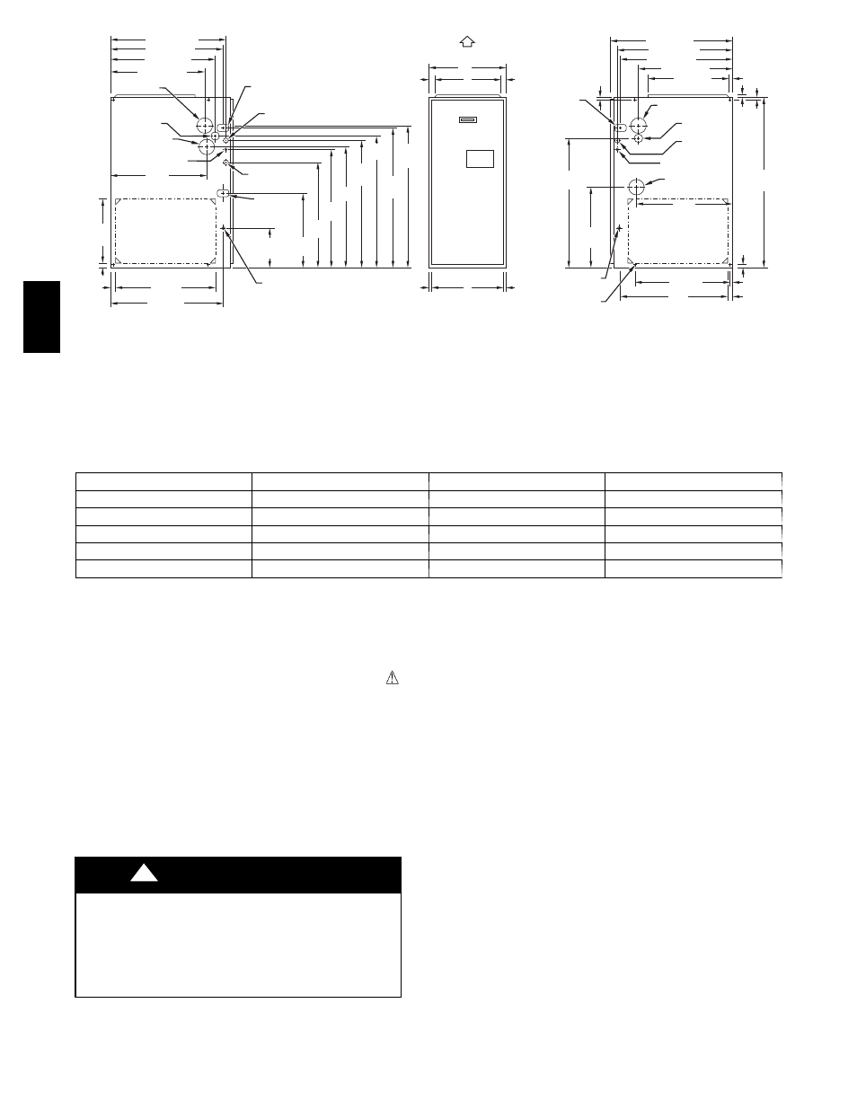
NOTES: 1. Minimum return-air openings at furnace, based on metal duct. If flex duct is used,
see flex duct manufacturerís recommendations for equivalent diameters.
2. Minimum return-air opening at furnace:
a. For 800 CFM–16-in. (406mm) round or 14
1
/
2
(368 mm)x 12-in. (305 mm) rectangle
.
b. For 1200 CFM–20-in. (508mm) round or 14
1
/
2
(368mm)x 19
1
/
2
-in. (495mm) rectangle
.
c. For 1600 CFM–22-in. (559mm) round or 14
1
/
2
(368mm)x 23
1
/
4
-in.(591mm) rectangle
.
d. For airflow requirements above 1800 CFM, see Air Delivery table in Product Data
literature for specific use of single side inlets. The use of both side inlets, a
combination of 1 side and the bottom, or the bottom only will ensure adequate
return air openings for airflow requirements above 1800 CFM.
17
5
⁄
16
"
24
1
⁄
2
"
27
9
⁄
16
"
TYP
27
5
⁄
8
"
29
11
⁄
16
"
TYP
30
13
⁄
16
"
32
5
⁄
8
"
TYP
33
1
⁄
4
"
TYP
CONDENSATE
DRAIN TRAP
LOCATION
(ALTERNATE
UPFLOW)
7
⁄
8
-IN. DIA (22mm)
ACCESSORY
POWER ENTRY
7
⁄
8
-IN. DIA (22mm)
POWER CONN
CONDENSATE DRAIN
TRAP LOCATION
(DOWNFLOW &
HORIZONTAL LEFT)
26
15
⁄
16
"
24
1
⁄
2
"
22
5
⁄
16
"
2-IN. (51 mm) COMBUSTION-
AIR CONN
1
⁄
2
-IN. (13mm) DIA
GAS CONN
2-IN (51mm)
.
VENT CONN
1
⁄
2
-IN. DIA (13mm)
THERMOSTAT ENTRY
22
11
⁄
16
"
SIDE INLET
23
1
⁄
4
" TYP
SIDE INLET
1
1
⁄
4
"
1"
OUTLET
26
15
⁄
16
"
28
1
⁄
2
"
22
5
⁄
16
"
19"
13
⁄
16
"
5
⁄
8
"
5
⁄
16
"
1"
39
7
⁄
8
"
22
1
⁄
4
" TYP
11
⁄
16
"
7
⁄
16
"
24
3
⁄
16
"
BOTTOM INLET
18
1
⁄
4
"
22
11
⁄
16
"
2-IN. (51mm)
COMBUSTION-AIR CONN
1
⁄
2
-IN. DIA (13mm)
GAS CONN
7
⁄
8
-IN. DIA (22mm)
POWER CONN
1
⁄
2
-IN. DIA (13 mm)
THERMOSTAT ENTRY
2-IN. (51 mm)
VENT CONN
DIMPLE LOCATORS
FOR HORIZONTAL
HANGING
14
1
⁄
2
"
TYP
SIDE INLET
9
7
⁄
16
"
TYP
26
15
⁄
16
" TYP
CONDENSATE
DRAIN LOCATION
(UPFLOW)
30
1
⁄
2
"
9
⁄
16
"
TYP
CONDENSATE
DRAIN LOCATION
(UPFLOW)
E
INLET
11
/
16
"
11
/
16
"
D
13
/
16
"
13
/
16
"
OUTLET
A
AIRFLOW
26
1
⁄
4
"
26
1
⁄
4
"
CONDENSATE DRAIN
TRAP LOCATION
(DOWNFLOW &
HORIZONTAL RIGHT)
OR ALTERNATE
1
⁄
2
-IN. DIA GAS CONN
(684 mm)
(667 mm)
(622 mm)
(567 mm)
(368 mm)
(32 mm)
(25mm)
(591 mm)
(684 mm)
(240 mm)
(439 mm)
(622 mm)
(700 mm)
(702 mm)
(754 mm)
(783 mm)
(829 mm)
(845 mm)
(21 mm)
(17 mm)
(17 mm)
(21 mm)
(775 mm)
(464 mm)
(14 mm)
(614 mm)
(565 mm)
(576 mm)
(483 mm)
(567 mm)
(667 mm)
(684 mm)
(724 mm)
(21 mm)
(16 mm)
(16 mm)
(1013 mm)
(25 mm)
(11 mm)
(25 mm)
A05124
Dimensions (In. / mm)
UNIT SIZE
A
D
E
060---14 / 042060
17---1/2 / 445
15---7/8 / 403
16 / 406
080---14 / 042080
21 / 533
19---3/8 / 492
19---1/2 / 495
080---20 / 060080
21 / 533
19---3/8 / 492
19---1/2 / 495
100---20 / 060100
21 / 533
19---3/8 / 492
19---1/2 / 495
120---20 / 060120
24---1/2 / 622
22---7/8 / 581
23 / 584
Fig. 2 -- Dimensional Drawing
In Canada, refer to the current editions of the National Standards
of Canada CAN/CSA--B149.1 and .2 Natural Gas and Propane
Installation Codes, and Canadian Electrical Code CSA C22.1
Recognize safety information. This is the safety--alert symbol
.
When you see this symbol on the unit and in instructions or
manuals, be alert to the potential for personal injury.
Understand the signal words DANGER, WARNING, and
CAUTION. These words are used with the safety--alert symbol.
DANGER identifies the most serious hazards which will result in
severe personal injury or death. WARNING signifies hazards
which could result in personal injury or death. CAUTION is
used to identify unsafe practices which may result in minor
personal injury or product and property damage. NOTE is used
to highlight suggestions which will result in enhanced
installation, reliability, or operation.
ENVIRONMENTAL HAZARD
Failure to follow this caution may result in environmental
polution.
Remove and recycle all components or materials (i.e., oil,
refrigerant, control boards, etc.) before unit final disposal.
CAUTION
!
The 355CAV Condensing Gas--Fired Furnaces are CSA
(formerly AGA and CGA) design--certified for natural and
propane gases (see furnace rating plate) and for installation in
alcoves, attics, basements, closets, utility rooms, crawlspaces, and
garages. The furnace is factory--shipped for use with natural gas.
A CSA listed gas conversion kit is required to convert furnace for
use with propane gas.
See Fig. 3 for required clearances to combustibles.
Maintain a 1--in. (25 mm) clearance from combustible materials
to supply air ductwork for a distance of 36 inches (914 mm)
horizontally from the furnace. See NFPA 90B or local code for
further requirements.
These furnaces SHALL NOT be installed directly on carpeting,
tile, or any other combustible material other than wood flooring.
These furnaces are suitable for installation in a structure built on
site or a manufactured building completed at final site. The
design of this furnace line is NOT CSA design--certified for
installation in recreation vehicles, manufactured (mobile) homes
or outdoors.
This furnace is designed for continuous return--air minimum
temperature of 60_F (16_C) db or intermittent operation down to
55_F
(13_C) db such as when used with a night setback
thermostat. Return--air temperature must not exceed 80_F (27_C)
db. Failure to follow these return air limits may affect reliability
of heat exchangers, motors and controls. (See Fig. 4.)
These furnaces are shipped with the drain and pressure tubes
connected for UPFLOW applications. Minor modifications are
required when used in DOWNFLOW, HORIZONTAL RIGHT,
or HORIZONTAL LEFT (supply--air discharge direction)
applications as shown in Fig. 1. See details in Applications
section.
355C
A
V