Caution, Warning – Bryant SERIES A 355CAV User Manual
Page 15
15
HORIZONTAL RIGHT
(SUPPLY--AIR DISCHARGE) APPLICATIONS
A horizontal right furnace application is where furnace blower is
located to the left of combustion and controls section of furnace,
and conditioned air is discharged to the right.
PROPERTY DAMAGE HAZARD
Failure to follow this caution may result in property
damage.
Local codes may require a drain pan under entire furnace
and condensate trap when a condensing furnace is used in
an attic application or over a finished ceiling.
CAUTION
!
NOTE: In Canada, installations shall be in accordance with
current NSCNGPIC and/or local codes.
NOTE: The auxiliary junction box (J--box ) MUST be relocated
to opposite side of furnace casing. (See Fig. 14.) See Electrical
Connection section for J--box relocation.
Condensate Trap Location
CAP
PLUG
COLLECTOR BOX
DRAIN TUBE (BLUE &
WHITE STRIPED)
INDUCER HOUSING
(MOLDED) DRAIN
TUBE (VIOLET)
COLLECTOR BOX TUBE (PINK)
COLLECTOR BOX
DRAIN TUBE (BLUE)
COLLECTOR BOX
EXTENSION TUBE
CONDENSATE
TRAP
COLLECTOR BOX
TUBE (GREEN)
AUXILIARY “J” BOX RELOCATED HERE
A07279
Fig. 14 -- Horizontal Right Tube Configuration
The condensate trap must be removed from the factory--installed
blower shelf location and relocated in selected application
location as shown in Fig. 2 or 14.
To relocate condensate trap from the blower shelf to desired
location, perform the following:
1. Remove three tubes connected to condensate trap.
2. Remove trap from blower shelf by gently pushing tabs in-
ward and rotating trap.
CARBON MONOXIDE POISONING HAZARD
Failure to follow this warning could result in personal
injury or death.
Casing hole filler cap must be installed in blower shelf hole
when condensate trap is relocated to prevent combustion
products being drawn in from appliances in the equipment
room.
!
WARNING
3. Install casing hole filler cap (factory--supplied in loose
parts bag) into blower shelf hole where trap was removed.
4. Install condensate trap into right--hand side casing hole by
inserting tube connection tabs through casing hole and ro-
tating until tabs snap into locking position.
5. Fill unused condensate trap casing holes with plastic filler
caps (factory--supplied in loose parts bag).
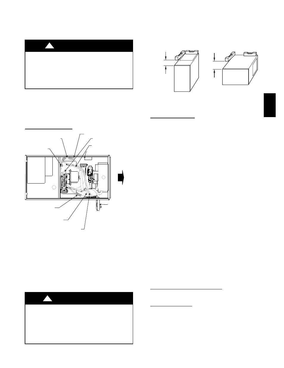
UPFLOW OR DOWNFLOW
HORIZONTAL
FRONT
FRONT
LEVEL (0”)
TO 1/2” (13mm)
MAX
MIN 1/4” (7mm)
TO 1/2” (13mm)
MAX
A02146
Fig. 15 -- Proper Condensate Drainage
Condensate Trap Tubing
NOTE: See Fig. 14 or tube routing label on main furnace door
to check for proper connections.
1. Collector Box Drain Tube
a. Remove factory--installed plug from LOWER collector
box drain tube (blue and white striped label).
b. Install removed clamp and plug into UPPER collector
box drain tube (blue label) which was previously connec-
ted to condensate trap.
c. Connect LOWER collector box drain tube (blue and
white striped label) to condensate trap. Tube does not
need to be cut.
d. Clamp tube to prevent any condensate leakage.
2. Inducer Housing Drain Tube
(a.)Remove factory--installed cap and clamp from
LOWER inducer housing drain connection.
(b.)Remove and discard UPPER (molded) inducer
housing drain tube which was previously con-
nected to condensate trap.
(c.)Install cap and clamp on UPPER inducer hous-
ing drain connection where molded drain tube
was removed.
(d.)Use inducer housing drain extension tube (violet
label and factory--supplied in loose parts bag) to
connect LOWER inducer housing drain connec-
tion to condensate trap.
(e.)Determine appropriate length, cut, and connect
tube to condensate trap.
(f.)Clamp tube to prevent any condensate leakage.
3. Relief Port Tube
Refer to Pressure Switch Tubing section for recommenda-
tions and procedures.
Condenste Trap Field Drain Attachment
Refer to Condensate Drain section for recommendations and
procedures.
Pressure Switch Tubing
One collector box pressure tube (pink label) is factory connected
to the pressure switch for use when furnace is installed in
UPFLOW or HORIZONTAL LEFT applications. This tube
MUST be disconnected and used for the condensate trap relief
port tube. The other collector box pressure tube (green label)
which was factory connected to the condensate trap relief port
connection MUST be connect to the pressure switch in
DOWNFLOW or HORIZONTAL RIGHT applications.
355C
A
V