Figure of terminal plate – RKI Instruments RM-5000 Series Indicator/Alarm Unit User Manual
Page 22
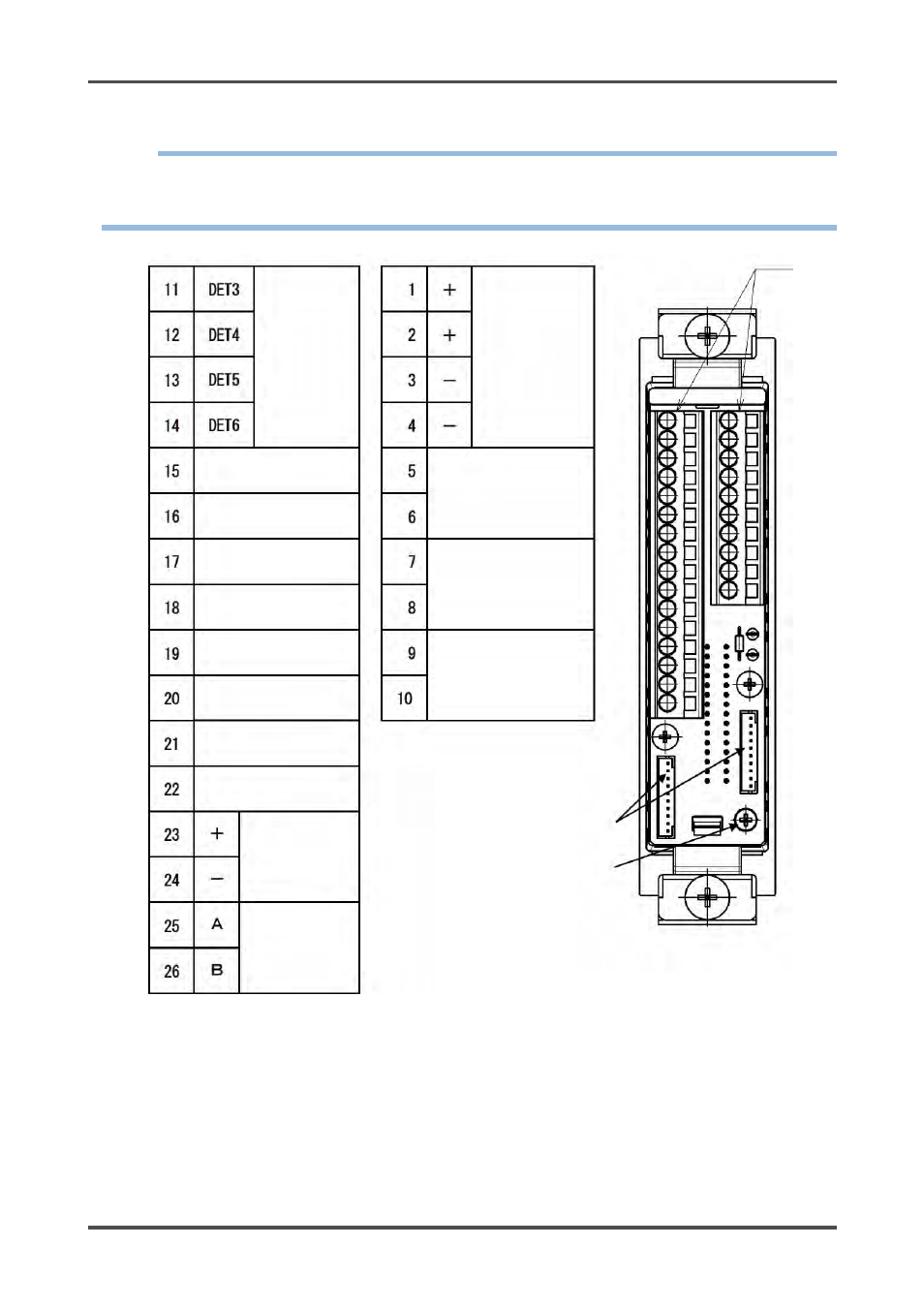
4 How to Use
4-5. How to wire
RM-5000
- 22 -
NOTE
Install the indicator/alarm unit in a single-unit case (option) or multi-unit case (option) before using it.
This section explains using the single-unit case.
For information on using the multi-unit case, see the operating manual of the multi-unit case.
*1: A signal to be used between the indicator/alarm unit and the buzzer unit TAN-5000 (option). This is not
used by the user.
*2: Output only if RS-485 (option) is mounted.
*3: Used for transition wiring for signals between devices when single-unit cases (option) are connected.
When this connector is used, no transition wiring between cases is required at the terminal plate.
Detector head
Reset signal input
(*3)
Test input (*3)
Buzzer stop
Signal input (*3)
Common (*3)
First alarm signal output
(*1, *3)
Fault alarm signal output
(*1, *3)
Buzzer signal output
(*1, *3)
Second alarm signal output
(*1, *3)
RS-485
input-output
(*2, *3)
Power input
24 VDC
First alarm contact output
Second alarm contact
output
Fault alarm contact output
Grounding
terminal
Connector for between
single-unit cases (*3)
Terminal plate
4 - 20 mA
output