Developing the desired driveshaft curve – Precision Turbo and Engine BigStuff3 GEN3 1st Gear Spark Retard with Traction Control System (SR2) User Manual
Page 14
Rev 1.0
14
The GEN3 “Replay” data acquisition system will graph of the amount of timing retard used during any given
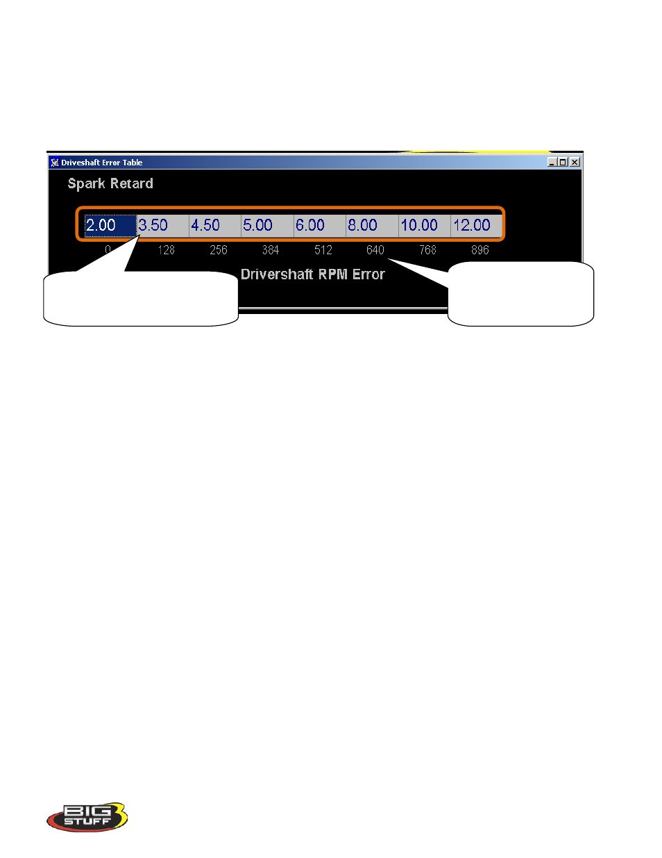
pass. The timing retard variable displayed in the replay is called “TorqRetard”. The GEN3 ECU uses the
timing retard values in the Driveshaft Error Table below to apply timing retard as a function of driveshaft
error. For example, if the GEN3 ECU determines (from driveshaft sensor used in the system) that the
driveshaft error is 896 rpm, based on the table below, the ECU will apply 12 degrees of timing retard until
the driveshaft error is bought back to zero.
In order for the SR
2
system to operate the following conditions must be met.
• The minimum RPM and TPS values in the “Boost Parameters” section above must be met.
• The timer enable wire must have 12V applied to it exactly when you want to start the timing
sequence. This can be accomplished by inverting the signal from the trans-brake or clutch switch.
• The SR
2
system requires that the timer enable and DAE trigger wires be on separate On/Off switches.
Note: The Timer Enable sequence will be reactivated, every time the throttle is closed and then opened again
(if you get off and then on the throttle again during a pass), until the “Blend” feature is active.
Developing the Desired Driveshaft Curve
The best method for developing a desired driveshaft curve is to make a pass and record the driveshaft speed.
Ideally, try to make the most aggressive pass possible without spinning the tires. Ensure that the following
items are in place before attempting a pass:
• Make sure the driveshaft speed sensor is installed and functioning correctly. If the sensor ouput is
erratic, switch the wires and/or check the sensor air gap, which should be between .080” and .100”.
•
Disable the Torque Management
system by un-checking box titled “Torque Control Enable”, in the
Torque Parameters table shown below.
“Driveshaft RPM Error” is
defined as the difference “error”
between the desired driveshaft
speed (TISS) and actual drive
shaft speed (TOSS).
The values in this table represent the amount of
timing retard applied (against the base spark
map) when the driveshaft error reaches each
RPM level shown