Pololu Jrk USB User Manual
Page 6
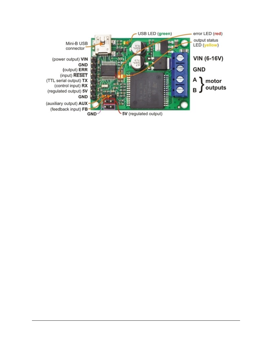
Pololu jrk 12v12 USB motor controller with feedback, labeled top view.
The Pololu jrk USB motor controller can connect to a computer’s USB port via a
(not included). The USB connection is used to configure the motor controller. It can
also be used to send commands to the motor controller, get information about the motor controller’s current state, and
send and receive TTL serial bytes on the TX and RX lines.
Power for the motor must be supplied to the jrk on the VIN and GND lines pictured on the right side of the diagram
above. Your power source must be capable of delivering the current your motor will draw. The jrk has reverse power
protection on the motor power input lines, so the board will not be damaged if the motor power inputs are accidentally
switched. If the VIN supply is not present, the jrk’s microcontroller can be powered directly from USB and perform
all of its functions except for driving the motor.
For the jrk 21v3, the input voltage should be 5–28 V (the recommended operating voltage is 8–28 V, but the jrk 21v3’s
motor driver has derated performance down to 5 V and transient protection to 40 V). The jrk 21v3’s motor driver can
supply a continuous 3 A with peaks up to 5 A.
For the jrk 12v12, the input voltage should be 6–16 V. The jrk 12v12’s motor driver can supply a continuous 12 A
with peaks up to 30 A.
The jrk has a linear voltage regulator that derives 5 V from the VIN supply. The 5 V supply is used as the internal
logic supply for the jrk and is also available at several pins for powering devices such as external microcontrollers and
feedback sensors (such as potentiometers). Because the regulator must dissipate excess power as heat, the available
output current is dependent on the input voltage: 50 mA is available for VIN up to 12 V; the available current drops
off linearly from 50 mA at 12 V to zero at 30 V.
The jrk has three indicator LEDs:
• The
green
USB LED indicates the USB status of the device. When the jrk is not connected to a computer via
the USB cable, the green LED will be off. When you connect the jrk to USB, the green LED will start blinking
slowly. The blinking continues until the jrk receives a particular message from the computer indicating that the
jrk’s USB drivers are installed correctly. After the jrk gets this message, the green LED will be on, but it will
flicker briefly when there is USB activity. The configuration utility constantly streams data from the jrk, so when
the configuration utility is running and connected to the jrk, the green LED will flicker constantly.
Pololu Jrk USB Motor Controller User's Guide
© 2001–2014 Pololu Corporation
1. Overview
Page 6 of 45