B. input options, Section 3.b – Pololu Jrk USB User Manual
Page 16
3.b. Input Options
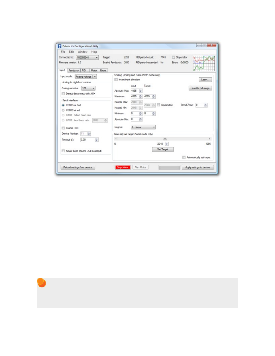
The Input tab of the Jrk Configuration Utility
The Input tab of the jrk configuration utility contains settings for how the feedback system (consisting of the jrk, a
motor and a feedback sensor) is externally controlled and monitored. Most importantly, there are three Input modes:
• Serial indicates that the jrk gets its target setting over a serial interface, either a virtual COM port or the TTL-
level serial port of the jrk, as explained in detail in
• Analog voltage is used when an analog voltage source, such as a potentiometer, connected to the RX line is
used to set the target. A signal level of 0 V on this line corresponds to an input value of 0, and signal level of 5 V
correponds to an input value of 4092.
• Pulse width is used when the system is to be controlled by the width of digital pulses, such as those output
by a radio-control (RC) receiver, measured on the RX line. In this input mode, the input value is the width of
the most recent pulse, in units of 2/3 μs. For example, a pulse width of 1500 μs corresponds to an input value
of 2250. This input interface accepts pulses from 400 to 2600 μs at a frequency between 10 and 150 Hz. The
jrk will only update the input value if it has received four valid pulses in a row, and it will generate the Input
invalid error if it goes more than 120 ms without updating the input value. The voltage of the high pulses must
be between 2 and 5 V.
Version 1.3 of the firmware for the Jrk 21v3 and the Jrk 12v12 contains a bug fix that improves the
reliability of the Pulse width input. The update is recommended for devices with an earlier firmware
version number, including all devices shipped before August 25, 2009. See
for upgrade
information.
Pololu Jrk USB Motor Controller User's Guide
© 2001–2014 Pololu Corporation
3. Configuring the Motor Controller
Page 16 of 45