Software installation, Input / output wiring – Paxton Net2 nano control unit User Manual
Page 3
Page 3
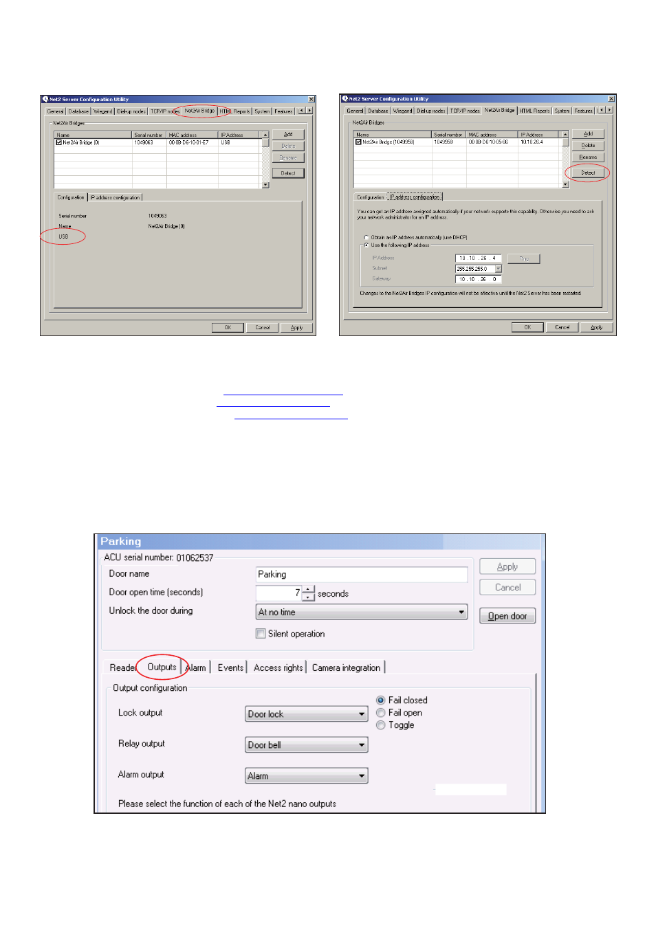
The Net2 software should be loaded on the controlling PC and at least one Net2Air bridge configured to
communicate with the unit.
Software installation
Full documentation is supplied with the Net2Air bridge unit and also on the website as follows:
X
AN1051 - Installing Net2 software <
http://paxton.info/1520 >
X
Ins-30084 - Net2Air USB bridge <
http://paxton.info/926 >
X
Ins-30085 - Net2Air Ethernet bridge <
http://paxton.info/920 >
INPUT / OUTPUT WIRING
Lock output - This is a transistor 'open drain' output, (not a voltage free contact) that has been designed
to simplify the wiring of the lock. It can be configured to operate in Fail lock, Fail unlock or toggle modes and
removes the need for additional links or diodes normally required when using a relay for output switching.
Relay output - This provides a set of volt free contacts to switch external devices.
Alarm output - This is a transistor driven output that switches to 0V when activated.
The Net2 nano has 3 outputs that can be configured in the Doors screen to perform different functions.
This flexibility means that a site that requires the Relay output (volt free contacts) for the door function can
configure the Lock output to drive a door bell.
Only ONE Net2Air USB bridge may be used per system. Multiple Net2Air Ethernet bridges may also be configured.