Control unit installation, Radio frequency – Paxton Net2 nano control unit User Manual
Page 2
Page 2
Control unit installation
Wire the components to the Access Control Unit (ACU) as shown on the first page. This will include:
- Reader/Keypad
- Electric Lock
- Power supply
- Any other optional components
Press the exit button or in the absence of an exit button, short the 0V and exit terminals together.
The lock relay LED will come on and the lock should release.
Lock output - This is a transistor 'open drain' output, (not a voltage free contact) that has been designed
to simplify the wiring of the lock. It can be configured to operate in Fail lock, Fail unlock or toggle modes and
removes the need for additional links or diodes normally required when using a relay for output switching.
Relay output - This provides a set of volt free contacts to switch external devices.
Alarm output - This is a transistor driven output that switches to 0V when activated.
Data transfer with wireless technology requires far more control and error checking than with a hard wired data
line connection. Net2 classic runs with a server that originates and controls all the communications on the data
line. This would not be efficient in a wireless environment.
We therefore give the Nano controller the active role. Each Nano is always active and transmits data bursts
(including a regular Heartbeat) every few seconds. The Net2 server then acts upon these requests for service.
The PC requires at least one Net2Air bridge to communicate with a Nano. This can be a local Net2Air USB bridge
(only one per system) and/or multiple Net2Air Ethernet bridge units connected to the PC via a TCP/IP connection.
Net2 nano / server operation
Net2Air wireless communication
There is NO Net2 nano detection function. It is recognised that there could be security issues if the wireless
units were detectable from outside the site. During installation, a Nano unit binds to a Net2Air bridge which will
then only talk to registered units. The Server Configuration Utility also has an ' Enable commissioning' mode which
can be turned off to inhibit Nano units being added.
Net2Air wireless control units are fully compatible with the hard wired Net2 range but there are several important
differences that need to be understood before installing wireless equipment. The most important of these is the
location of the control units and their bridge components.
These principles are therefore explained first before we move on to the control unit itself.
The reader's default indication has all the LED's on. Access granted is denoted with a single flashing Green LED.
Access Denied is a single flashing Red LED.
A Net2 nano ACU or a Hands free interface cannot be installed in a Metal cabinet as this would block the RF signal
used for the Net2Air wireless technology.
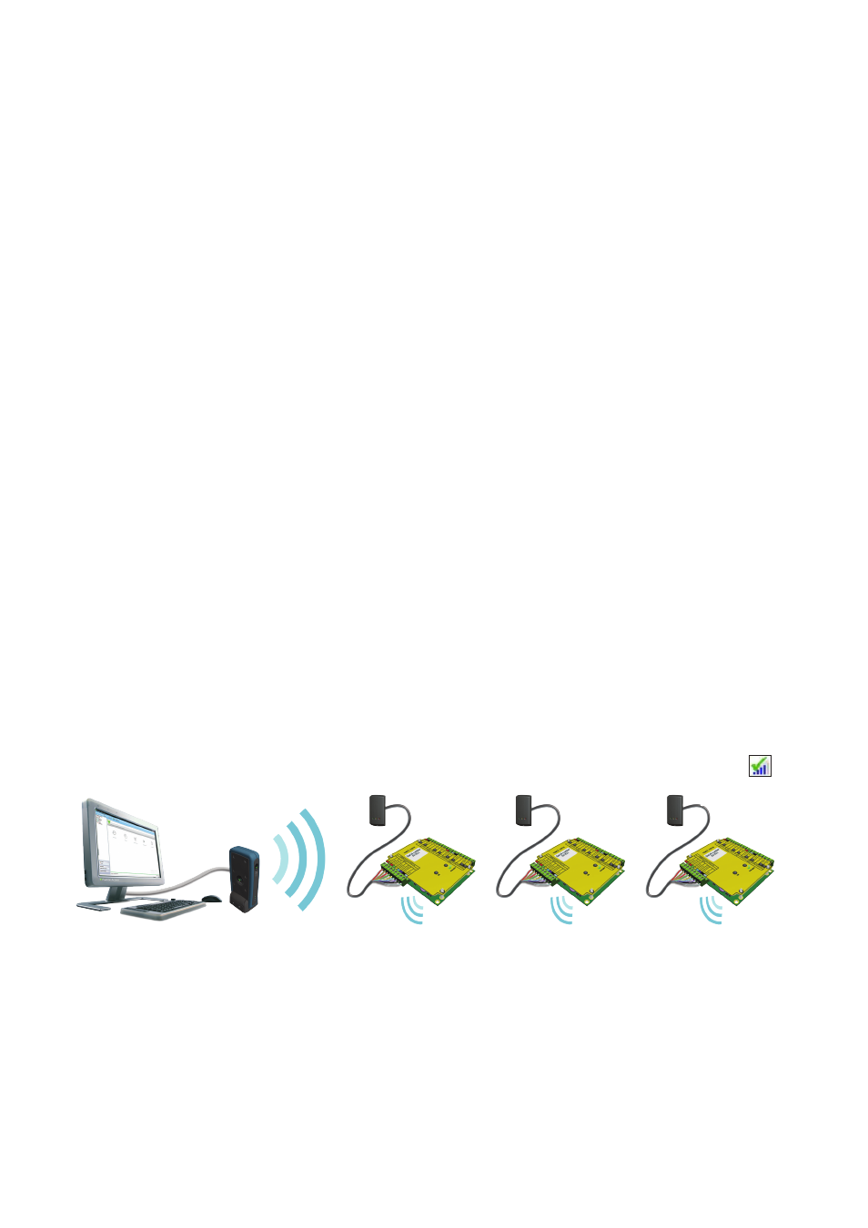
Reader
Control unit
Net2 Server
An entry is then made on the Doors screen and a special icon is used to denote the wireless connection.
Radio frequency
This product should not be installed within 3 metres of other wireless equipment operating on a 2.4Ghz frequency.
To ensure optimum performance other wireless networks should avoid WiFi channels 11, 12 and 13 to reduce the
possibility of interference.