Standard non-separating mechanical interface, Optional mechanical interfaces – Orbital Minotaur VI User Manual
Page 65
Minotaur IV • V • VI User’s Guide
Section 5.0 – Payload Interfaces
degree marks are counterclockwise when forward looking aft. The positive X-axis is forward along the
vehicle longitudinal centerline, the positive Z axis is along the 180 deg angular, and the positive Y axis is
along the 90 deg angular station, and completes the orthogonal system. The origin of the LV coordinate
system is centered at the Stage 1 nozzle exit plane of the LV and the vehicle centerline (X = 0.0 in., Y =
0.0 in., Z = 0.0 in.).
5.2.2. Orbital Supplied Mechanical Interface Control Drawing
Orbital will provide a toleranced Mechanical Interface Control Drawing (MICD) to the payload contractor to
allow accurate machining of the fastener holes. The Orbital provided MICD is the only approved
documentation for drilling the payload interface.
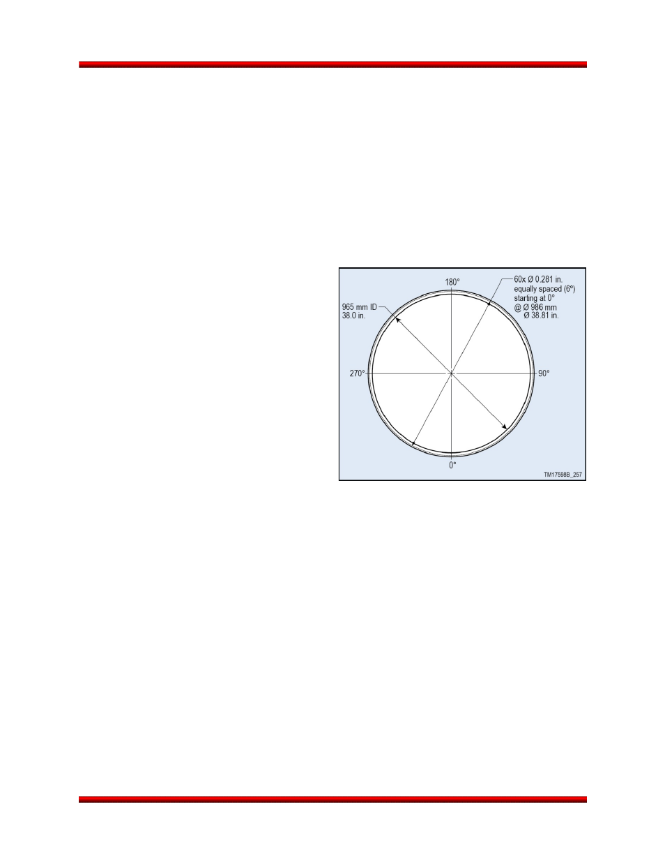
5.2.3. Standard Non-Separating Mechanical Interface
Orbital’s payload interface design provides a
standard interface that will accommodate multiple
payload configurations. The Minotaur IV baseline is
for payloads to provide their own separation
system or for payloads that will not separate. The
standard interface is a 986 mm (38.81 in.) diameter
bolted interface. A butt joint with 60 holes
(0.281 in. diameter) designed for ¼ in. fasteners is
the payload mounting surface as shown in Figure
5.2.3-1.
5.2.4. Optional Mechanical Interfaces
Alternate or multiple payload configurations can be
accommodated with the use of a variety of payload
adapter fittings as listed in Table 5.2.4-1. The
Minotaur IV family of Launch Vehicles allows
flexibility in mounting patterns and configurations
(Figure 5.2.4-1).
Figure 5.2.3-1. Standard, Non-separating 38.81”
Diameter Payload Mechanical Interface
Release 2.0
June 2013
50