Optional 110” fairing, 110” fairing payload dynamic design envelope – Orbital Minotaur VI User Manual
Page 62
Minotaur IV • V • VI User’s Guide
Section 5.0 – Payload Interfaces
5.1.2. Optional 110” Fairing
A larger 110” diameter fairing design is available as an enhancement to accommodate payloads larger
than those that can be fit in the standard 92” diameter fairing. The larger fairing is primarily intended for
use by Minotaur VI and VI+ payloads, with limited applications available on other Minotaur configurations.
Flying the 110” fairing will result in approximately 200 kg performance impact and reduced launch
availability. The fairing, composite materials, structural testing, separation and deployment systems are
similar to those of the heritage 92” fairing. The only appreciable change to the deployment system is the
use of a new thruster bracket that attaches to the boat-tail portion of the aft end of the fairing. Deployment
margin is actually improved for the 110” fairing vs. the standard fairing because the larger diameter of the
110” fairing draws the fairing mass radially outward and closer to the hinge pivot points.
Performance runs with the 110” fairing are included within Section 3.0.
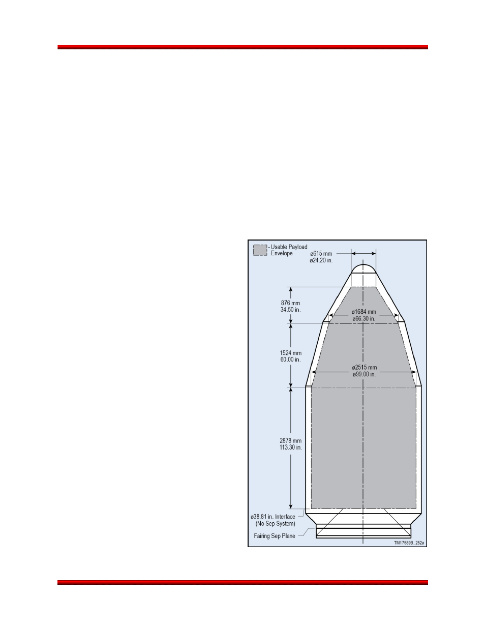
5.1.2.1. 110” Fairing Payload Dynamic Design Envelope
Figure 5.1.2.1-1 shows the maximum dynamic envelope available in the larger 110” fairing for the payload
during powered flight. The dynamic envelope shown accounts for fairing and vehicle structural deflections
only. The payload contractor must consider
deflections due to spacecraft design and
manufacturing tolerance stack-up within the
dynamic envelope. Proposed payload dynamic
envelope violations must be approved by Orbital
via the ICD.
No part of the payload may extend aft of the
payload interface plane without specific Orbital
approval. Incursions below the payload interface
plane may be approved on a case-by-case basis
after additional verification that the incursions do
not cause any detrimental effects. Vertices for
payload deflection must be given with the Finite
Element Model to evaluate payload dynamic
deflection with the Coupled Loads Analysis (CLA).
The payload contractor should assume that the
interface plane is rigid; Orbital has accounted for
deflections of the interface plane. The CLA will
provide final verification that the payload does not
violate the dynamic envelope.
Figure 5.1.2.1-1. Dynamic Envelope for Optional
110” Fairing with Standard 38” PAF
Release 2.0
June 2013
47