Payload interfaces, Payload fairing, 92” standard minotaur fairing – Orbital Minotaur VI User Manual
Page 61: 92” fairing payload dynamic design envelope
Minotaur IV • V • VI User’s Guide
Section 5.0 – Payload Interfaces
5. PAYLOAD INTERFACES
This section describes the available mechanical, electrical and Launch Support Equipment (LSE)
interfaces between the Minotaur launch vehicle and the payload.
5.1. Payload Fairing
5.1.1. 92” Standard Minotaur Fairing
Orbital’s flight proven 92-inch diameter payload fairing is used to encapsulate the payload, provide
protection and contamination control during ground handling, integration operations and flight. The fairing
is a bi-conic design made of graphite/epoxy face sheets with aluminum honeycomb core. The two halves
of the fairing are structurally joined along their longitudinal interface using Orbital’s low contamination
frangible joint system. An additional circumferential frangible joint at the base of the fairing supports the
fairing loads. At separation, a gas pressurization system is activated to pressurize the fairing deployment
thrusters. The fairing halves then rotate about external hinges that control the fairing deployment to
ensure that payload and launch vehicle clearances are maintained. All elements of the deployment
system have been demonstrated through numerous ground tests and flights.
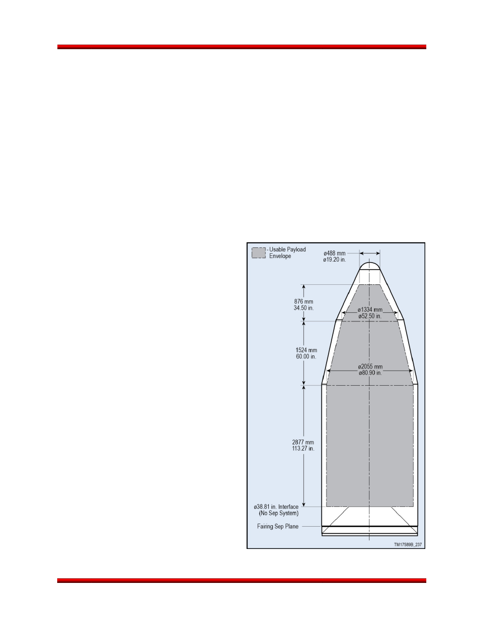
5.1.1.1. 92” Fairing Payload Dynamic Design
Envelope
The fairing drawing in Figure 5.1.1.1-1 shows the
maximum dynamic envelope available in the
standard MIV configuration for the payload during
powered flight. The dynamic envelope shown
accounts for fairing and vehicle structural
deflections only. The payload contractor must
consider deflections due to spacecraft design and
manufacturing tolerance stack-up within the
dynamic envelope. Proposed payload dynamic
envelope violations must be approved by Orbital
via the ICD.
No part of the payload may extend aft of the
payload interface plane without specific Orbital
approval. Incursions below the payload interface
plane may be approved on a case-by-case basis
after additional verification that the incursions do
not cause any detrimental effects. Vertices for
payload deflection must be given with the Finite
Element Model to evaluate payload dynamic
deflection with the Coupled Loads Analysis (CLA).
The payload contractor should assume that the
interface plane is rigid; Orbital has accounted for
deflections of the interface plane. The CLA will
provide final verification that the payload does not
violate the dynamic envelope.
Figure 5.1.1.1-1. Dynamic Envelope for
Standard 92” Fairing with Standard 38” PAF
Release 2.0
June 2013
46