Operation, Turning on the lamps, Auxiliary output receptacles – Multiquip T12D50SA User Manual
Page 27
LT12D50SA LIGHT TOWER • OPERATION MANUAL — REV. #0 (03/16/09) — PAGE 27
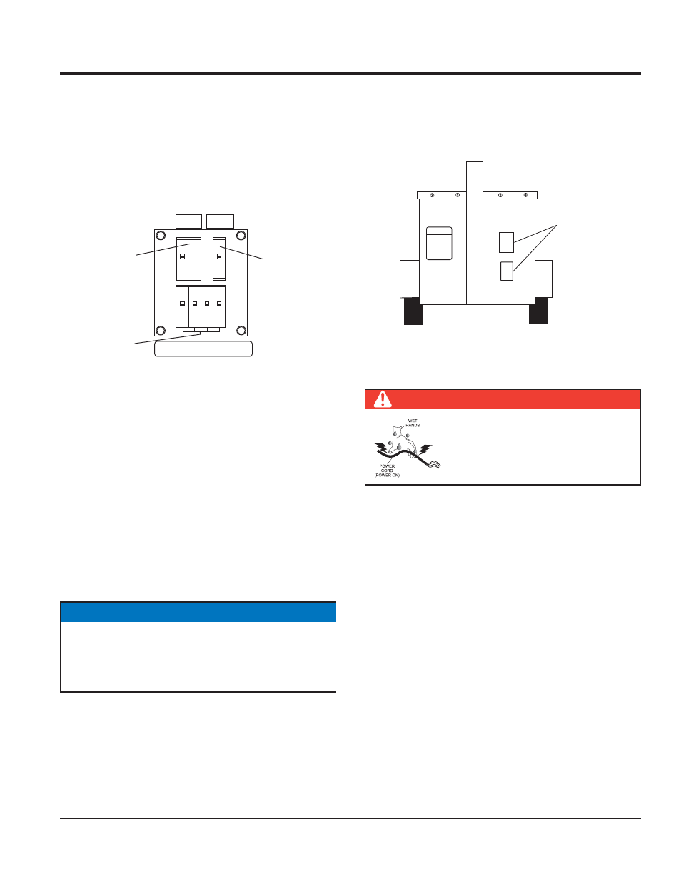
TURNING ON THE LAMPS
The main circuit breaker (30 amps), and 4 lamp circuit
breakers (15 amps each) are located on the upper control
panel (Figure17).
Place the main circuit breaker (Figure 17) on the control
1.
panel to the ON position.
Control Panel Circuit Breakers
Figure 17.
Set lamp circuit breaker #1 on the control panel to the
2.
ON position.
Wait a few minutes for the ballast to activate. Observe
3.
that lamp #1 is ON.
Repeat steps 2 and 3 for lamps 2 through 4.
4.
If all the lamp circuit breakers are in the ON position
5.
(up), then all of the lights should be on.
If any of the lamps are not on, refer to the troubleshooting
6.
section of this manual.
Close all cabinet doors.
7.
AUXILIARY
RECEPTACLE
CIRCUIT
BREAKER
LAMP
CIRCUIT
BREAKERS
MAIN
CIRCUIT
BREAKER
LIGHT CONTROL/BREAKER
15A
AUX
BREAKER
30A
MAIN
BREAKER
NOTICE
NEVER operate the light tower with the engine
compartment doors open. Operation with the doors
open may cause insuffi cient cooling to the unit, and
damage may result.
AUXILIARY OUTPUT RECEPTACLES
The light tower is equipped with auxiliary output receptacle
plates with wiring ready to install auxiliary receptacles
(Figure 18).
Auxiliary Output Receptacles
Figure 18.
DOCUMENTATION
BOX
FRONT
VIEW
AUXILIARY
OUTPUT
RECEPTACLES
15 AMPS
DANGER
NEVER grab or touch a live power cord
with wet hands. The possibility exists
of electrical shock, electrocution, and
even death!
OPERATION