Output terminal panel connections – Multiquip DCA20SPXU2D User Manual
Page 25
DCA20SPXU2D 60 HZ GENERATOR • OPERATION AND PARTS MANUAL — REV. #1 (03/25/11) — PAGE 25
OUTPUT TERMINAL PANEL CONNECTIONS
UOV TERMINAL OUTPUT VOLTAGES
240/120V outout voltages can be obtained using the output
terminal lugs.
The voltage regulator (VR), Figure 15 allows the user to
increase or decrease the selected voltage.
1Ø-240 Output Terminal Voltage
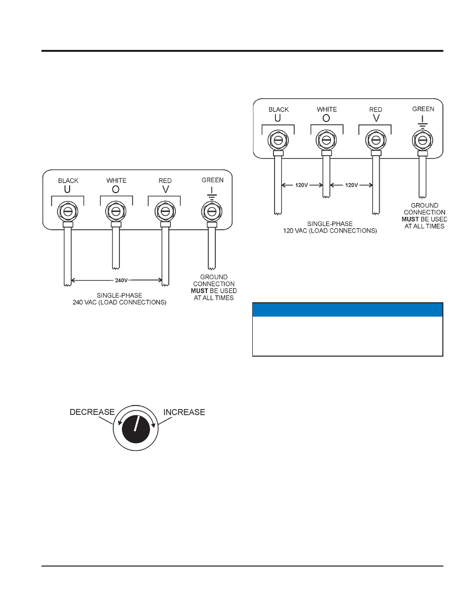
1. Connect the load wires to the output terminal lugs as
shown in Figure 14.
Figure 14. Output Terminal Lugs
1Ø-240 Volt Connections
2. Turn the voltage regulator knob (Figure 15) clockwise
to increase voltage output, turn counterclockwise to
decrease voltage output. Use voltage regulator
adjustment knob whenever fi ne tuning of the output
voltage is required.
Figure 15. Voltage Regulator Knob
1Ø-120 Output Terminal Voltage
1. Connect the load wires to the output terminal lugs as
shown in Figure 16.
Figure 16. Output Terminal Lugs
1Ø-120 Volt Connections
2. Turn the voltage regulator knob (Figure 15) clockwise
to increase voltage output, turn counterclockwise to
decrease voltage output.
NOTICE
ALWAYS make sure that the connections to the UOV
terminals are secure and tight. The possibility of arcing
exists, that could cause a fi re.