Load application/generator output, Single phase load, Generator amperage – Multiquip DCA20SPXU2D User Manual
Page 24
PAGE 24 — DCA20SPXU2D 60 HZ GENERATOR • OPERATION AND PARTS MANUAL — REV. #1 (03/25/11)
LOAD APPLICATION/GENERATOR OUTPUT
SINGLE PHASE LOAD
Always be sure to check the nameplate on the generator
and equipment to insure the wattage, amperage, frequency,
and voltage requirements are satisfactorily supplied by the
generator for operating the equipment.
Generally, the wattage listed on the nameplate of the
equipment is its rated output. Equipment may require
130—150% more wattage than the rating on the nameplate,
as the wattage is infl uenced by the effi ciency, power factor
and starting system of the equipment.
WATTS = VOLTAGE x AMPERAGE
The power factor of this generator is 0.8. See Table 5 below
when connecting loads.
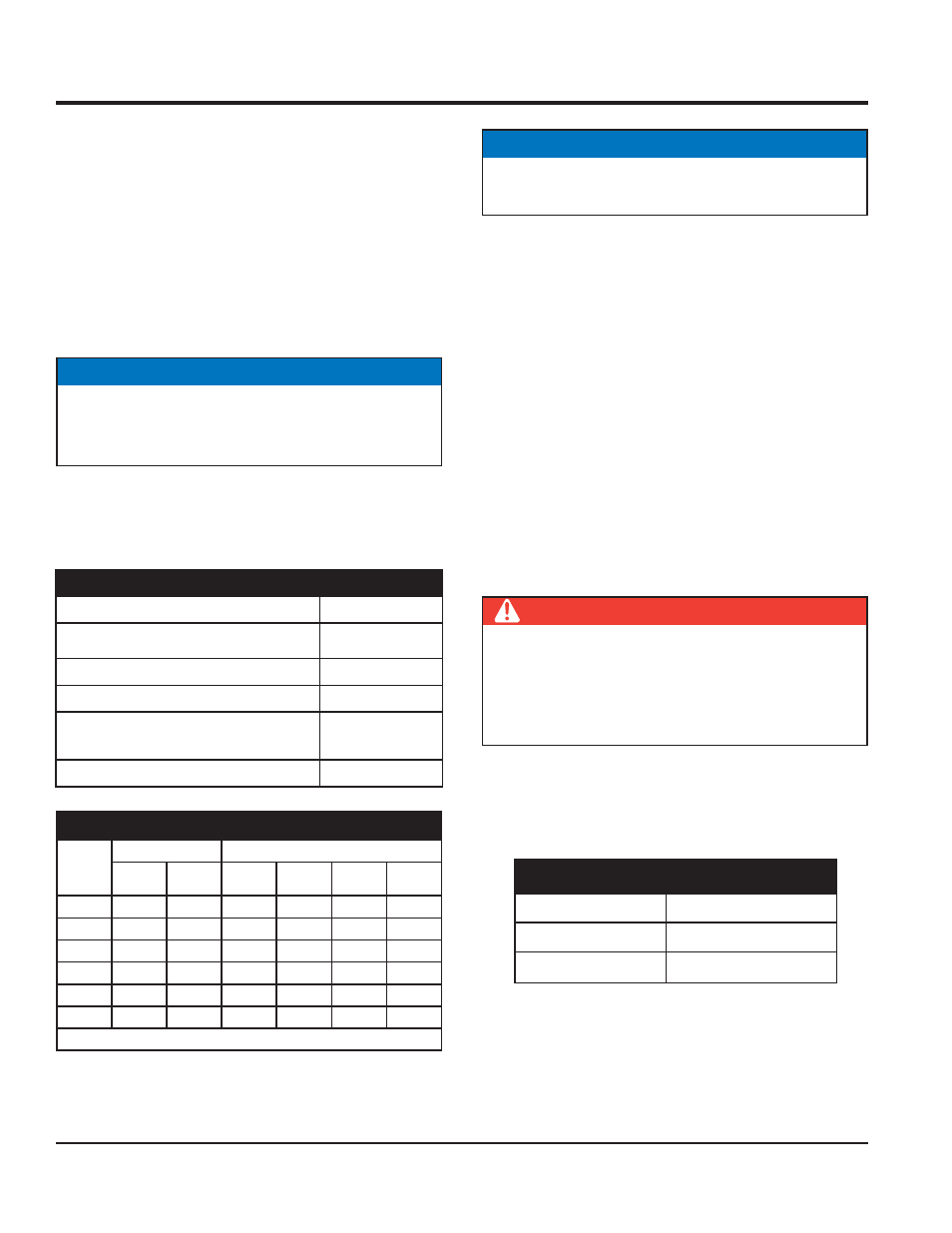
Table 6. Cable Selection (60 Hz, Single Phase Operation)
Current
in
Amperes
Load in Watts
Maximum Allowable Cable Length
At 100
Volts
At 200
Volts
#10 Wire
#12 Wire
#14 Wire
#16 Wire
2.5
300
600
1000 ft.
600 ft.
375 ft.
250 ft.
5
600
1200
500 ft.
300 ft.
200 ft.
125 ft.
7.5
900
1800
350 ft.
200 ft.
125 ft.
100 ft.
10
1200
2400
250 ft.
150 ft.
100 ft.
15
1800
3600
150 ft.
100 ft.
65 ft.
20
2400
4800
125 ft.
75 ft.
50 ft.
CAUTION: Equipment damage can result from low voltage
NOTICE
If wattage is not given on the equipment’s name plate,
approximate wattage may be determined by multiplying
nameplate voltage by the nameplate amperage.
Table 5. Power Factor By Load
Type of Load
Power Factor
Single-phase induction motors
0.4-0.75
Electric heaters, incandescent lamps
1.0
Fluorescent lamps, mercury lamps
0.4-0.9
Electronic devices, communication
equipment
1.0
Common power tools
0.8
An inadequate size connecting cable which cannot carry the
required load can cause a voltage drop which can burn out
the appliance or tool and overheat the cable. See Table 6
When connecting a resistance load such as an
incandescent lamp or electric heater, a capacity of up to
the generating set’s rated output (kW) can be used.
When connecting a fl uorescent or mercury lamp, a
capacity of up to the generating set’s rated output (kW)
multiplied by 0.6 can be used.
When connecting an electric drill or other power tools,
pay close attention to the required starting current
capacity.
When connecting ordinary power tools, a capacity of up to
the generating set’s rated output (kW) multiplied by 0.8 can
be used.
Generator Amperage
Table 7 shows the maximum amps the generator can
provide. DO NOT exceed the maximum amps as listed.
NOTICE
Motors and motor-driven equipment draw much greater
current for starting than during operation.
DANGER
Before connecting this generator to any building’s
electrical system, a licensed electrician must install
an isolation (transfer) switch. Serious damage to
the building’s electrical system may occur without this
transfer switch.
Table 7. Generator Maximum Amps
Rated Voltage
Maximum Amps
1Ø 120 Volt
83 X 2 amps (4 wire)
1Ø 240 Volt
83 amps (4 wire)