Maintenance, Installing pans onto finisher blades, Long-term storage – Multiquip J36E2 User Manual
Page 28: Variable speed pulley general description
page 28 — J36e2 elecTric WalK-BeHiND TrOWel • OperaTiON aND parTs maNUal — rev. #0 (07/24/12)
iNsTalliNg paNs ONTO FiNisHer BlaDes
These round discs, sometimes referred to as "pans", attach
to the spiders arms and allow early floating on wet concrete
and easy movement from wet to dry areas. They are also
very effective in embedding large aggregates and surface
hardeners.
Refer to Figure 28 when installing pans onto finisher blades.
Figure 28. Z-Clip Finisher Pan Installation
1. Lift trowel just enough to slide pan under blades. Lower
finisher onto pan with blades adjacent to Z-Clips.
2. Rotate blades into position under Z-Clips. Ensure that
the blades are rotated in the direction of travel when
the machine is in operation or use the engine to rotate
the blades into position.
3. Attach the blade tie-downs to the far side of the Z-Clip
brackets with tie-down knobs as shown in Figure 28.
4. Check to make certain that the blade edges are
secured under the Z-Clips and the tie-downs are
secured completely over the edges of the blade bar
before the machine is put back into operation.
lONg-Term sTOrage
For storage of the trowel for over 30 days, the following is
required:
Clean all external parts of the trowel with a cloth.
Cover the trowel and store in a clean, dry place.
BLADE ASSEMBLY
Z-CLIP, PAN
TIE-DOWN, BLADE
KNOB, TIE-DOWN
Z-CLIP PANS
MaintenanCe
variaBle speeD pUlley
general Description
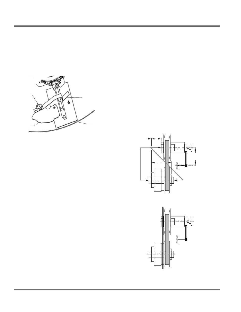
A fixed center distance compound drive consists (Figure 29)
of one cam stabilized automatic variable pulley, one manually
controlled pulley and a standard "V" belt or a variable speed
belt.
The speed adjustment is accomplished by turning the
leadscrew of the manually controlled pulley. As the faces
contract, the belt is forced to a larger diameter in the
manual pulley and consequently to a smaller diameter in
the automatic pulley.
Compound center distance drives may be "C" mounted,
both driving and driven shafts pointed in the same direction,
or "Z" mounted, driving and driven shafts opposed.
The manually controlled pulley must be mounted on the
driver shaft.
Figure 29. Pulley Orientation
DRIVER PULLEY
DRIVEN PULLEY
“Z” MOUNTED
I
“MAX”
L
J
“C” MOUNTED
STRAIGH
T EDGE