Maintenance, Spider removal, Changing blades – Multiquip J36E2 User Manual
Page 25
J36e2 elecTric WalK-BeHiND TrOWel • OperaTiON aND parTs maNUal — rev. #0 (07/24/12) — page 25
spiDer remOval
Remove the spider assembly from the gearbox shaft as
follows:
1. Locate the cone point square head set screw
(Figure 22) and attached jam nut found on the side of
the spider assembly.
2. Loosen the jam nut and cone point square head set
screw.
3. Carefully lift the upper trowel/gearbox assembly off of
the spider assembly. A slight tap with a rubber mallet
may be necessary to dislodge the spider from the main
shaft of the gearbox.
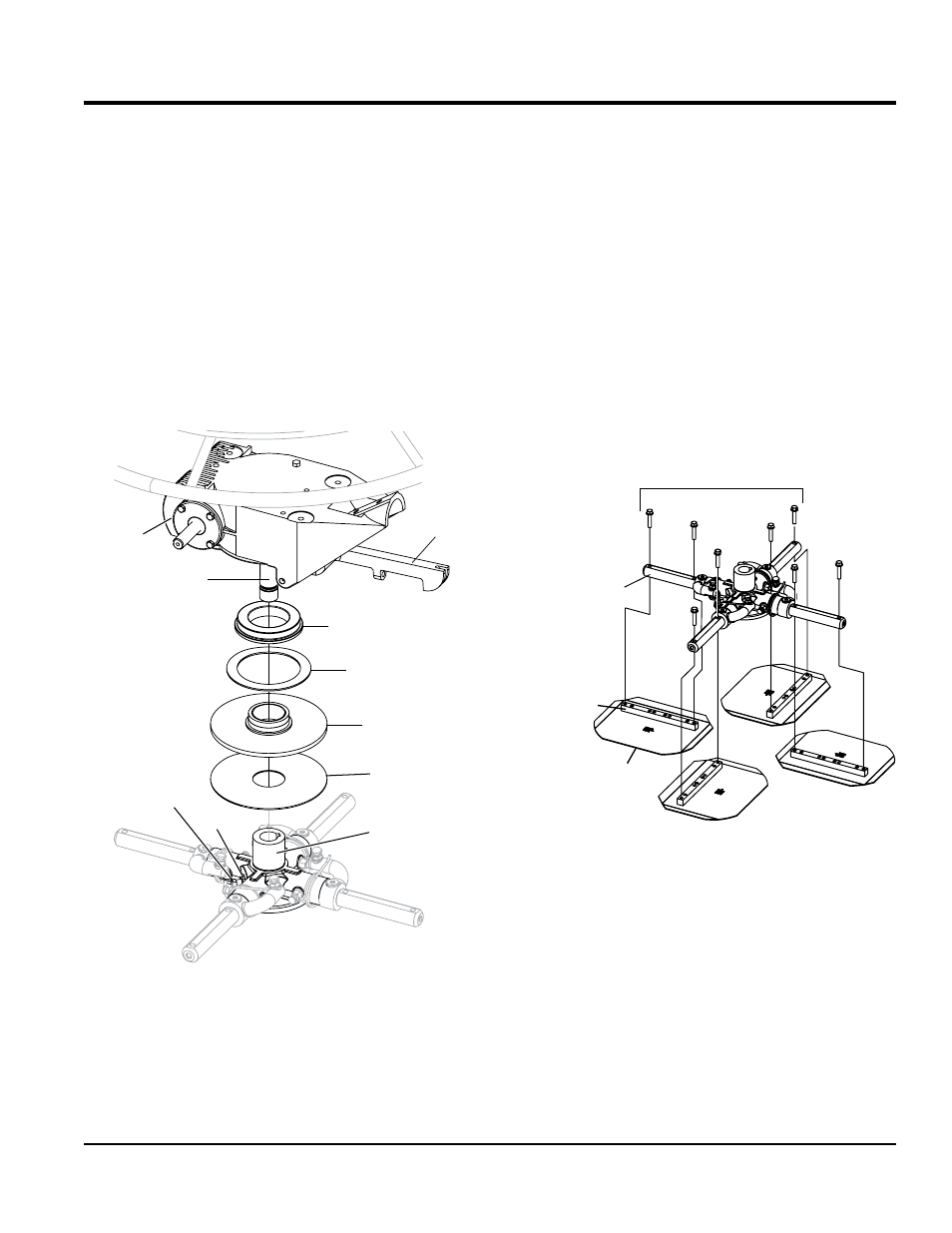
Figure 22. Spider Removal
GEARBOX
GEARBOX
SHAFT
THRUST COLLAR
BEARING
THRUST COLLAR
W/BUSHING
WEAR RING
LOWER WEAR
PLATE
SPIDER PLATE
JAM
NUT
SET SCREW
(CONE POINT SQ.HD.)
YOKE ARM
MaintenanCe
cHaNgiNg BlaDes
It is recommended that
all the blades on the trowel
are changed at the same time. If only one or some of the
blades are changed, the machine will not finish concrete
consistently and the machine may wobble or bounce.
Perform the following procedure when changing blades:
Please note the blade orientation on the trowel arm before
removing.
1. Lift the trowel up, placing blocks under the main guard
ring to support it.
2. Remove the bolts and lock washers from all the towel
arms, and then remove the blades as shown in
Figure 23.
Figure 23. Blade Removal
3. Wire brush and remove all concrete and debris from
all six sides of each of the four trowel arms. This is
important to properly seat the new blades.
4. Install the new blades, maintaining the proper blade
orientation for direction of rotation.
5. Reinstall the bolts and lock washers.
TROWEL ARM
BLADE
ATTACHMENT
SCREWS
TROWEL
BLADE
BLADE
ATTACHMENT
BAR