Maintenance, Trowel arm removal, Checking trowel arm straightness – Multiquip J36E2 User Manual
Page 26: Trowel arm lever adjustment
page 26 — J36e2 elecTric WalK-BeHiND TrOWel • OperaTiON aND parTs maNUal — rev. #0 (07/24/12)
MaintenanCe
TrOWel arm remOval
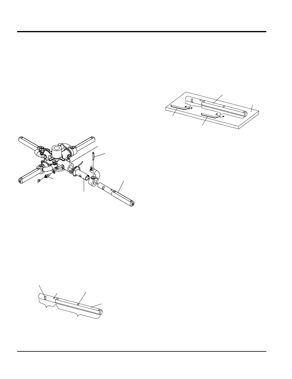
1. Each trowel arm is held in place at the spider plate
by a hex head bolt (zerk grease fitting) and a roll
pin. Remove both the hex head bolt and the roll
pin (Figure 24) from the spider plate.
2. Remove the trowel arm from the spider plate.
3. Should the trowel arm inserts ( bushing ) come out with
the trowel arm, remove the bushing from the trowel arm
and set aside in a safe place. If the bushing is retained
inside the spider plate, carefully remove the bushing
4. Examine the trowel arm bushing insert (Figure 24),
clean if necessary. Replace bushing if out of round or
worn.
Figure 24. Trowel Arm Removal
cHecKiNg TrOWel arm sTraigHTNess
Trowel arms (Figure 25) can be damaged by rough
handling, such as dropping the trowel on the pad, or by
striking exposed plumbing, forms, or rebar while in
operation. A bent trowel arm will not allow the trowel to
operate in a smooth fluid rotation. If bent trowel arms are
suspect, check for flatness as follows:
Figure 25. Trowel Arm
TROWEL
ARM
ROLL PIN
SPIDER PLATE
ZERK
GREASE
FITTING
CAP
BUSHING
TROWEL ARM
ROUND SHAFT
SECTION
ROLL PIN
HOLE
BLADE ATTACHMENT
BOLT HOLE
FLAT OF HEXAGONAL
SHAFT (TOP OF ARM)
LEVER
MOUNTING
SLOT
TROWEL ARM
HEXAGONAL (HEX)
SHAFT SECTION
1. Use a thick steel plate, granite slab or any surface
which is true and flat, to check all six sides of each
trowel arm for flatness (Figure 26).
2. Check each of the six sides of the trowel arm (hex
section). A feeler gauge of .004 inch (0.10 mm) should
not pass between the flat of the trowel arm and the test
surface along its length on the test surface.
Figure 26. Checking Trowel Arm Flatness
3. Next, check the clearance between the round shaft
and the test surface as one of the flat hex sections of
the arm rests on the test surface. Rotate the arm to
each of the flat hex sections and check the clearance
of the round shaft. Use a feeler gauge (Figure 27) of
.005 inch (0.127 mm). Each section should have the
same clearance between the round of the trowel arm
shaft and the test surface.
4. If the trowel arm is found to be uneven or bent, replace
the trowel arm.
TrOWel arm lever aDJUsTmeNT
The easiest and most consistent wASSY. to adjust the
trowel arm lever is to use the Trowel Arm Adjustment
Fixture (P.N. 1817).
As each trowel arm is locked into the fixture, the arm bolt
is adjusted to where it contacts a stop on the fixture. This
will consistently adjust all of the trowel arms, keeping the
finisher as flat and evenly pitched as possible.
This fixture will allow consistent adjustment of the trowel
arm lever. It comes with all the hardware necessary to
properly accomplish this maintenance and instructions on
how to properly utilize this tool. Adjusting the trowel arm
lever without a fixture requires a special talent.
Perform the following procedure when adjusting the trowel
arm lever:
TROWEL
ARM
TROWEL
ARM
FLAT TEST
SURFACE
FEELER GAUGE
(.004 IN/0.10 MM)
FEELER GAUGE
(.005 IN/0.127 MM)