Assembly and installation – Multiquip J36E2 User Manual
Page 18
page 18 — J36e2 elecTric WalK-BeHiND TrOWel • OperaTiON aND parTs maNUal — rev. #0 (07/24/12)
5. Using a wrench, tighten the brass set #2 nut up against
the yoke boss. This will lock the cable in place.
6. Use a wrench and finish tightening the brass set #1
nut up against the yoke boss.
gearbox Oil
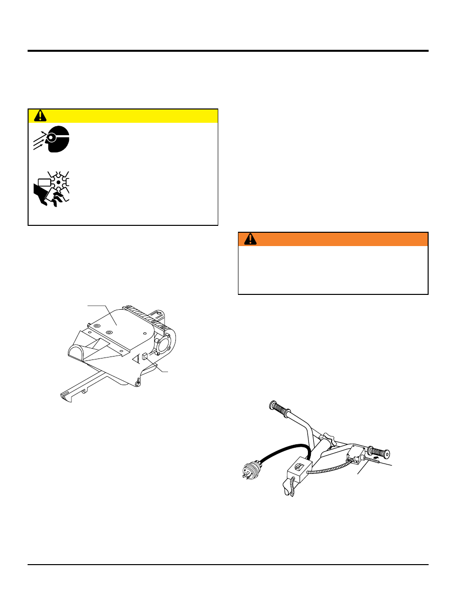
1. Determine if the gearbox oil is low by removing the oil
plug located on the side of the gearbox. (Figure 8) This
plug will be marked by the "check" decal. The correct
level of the lubrication oil should be to the bottom of
the fill plug.
Figure 8. Gearbox
2. If lubrication oil begins to seep out as the drain plug
is being removed, then it can be assumed that the
gearbox has a sufficient amount of oil.
3. If lubrication oil does not seep out as the drain plug
is being removed, fill with type ISO 680 (P/N 10139)
gearbox lubricant oil until the oil filler hole overflows.
caUTiON
alWays wear approved eye and hearing
protection before operating the trowel.
Never place hands or feet inside the
guard rings while the electric motor is
running.
alWays remove power from the
electric motor before performing any kind of
maintenance on the trowel.
OIL FILL
PLUG
GEARBOX
asseMbly and installatiOn
v-Belt check
A worn or damaged V-belt can adversely affect the
performance of the trowel. If a V-belt is defective or worn
simply replace the V-belt as outlined in the maintenance
section of this manual.
Belt guard check
Check for damage, loose or missing hardware.
Blade check
Check for worn or damaged blades. Check to see if one
blade is worn out while the others look new. If this is
the case there could be a blade pitch problem. Refer to
the maintenance section of this manual for blade pitch
adjustment procedure. Replace any worn blades.
Operator presence ON/OFF lever switch
This trowel has been equipped with an operator presence
ON/OFF lever switch (Figure 9). This switch should be
tested every time the motor is started.
The purpose of this switch is to stop the electric motor in
a runaway. situation, (i.e. the operator releasing the handle
during operation).
Figure 9. Operator Presence Switch
WarNiNg
Never disable or disconnect the safety "operator
presence" ON/OFF lever switch. It is provided for
operator safety. Injury may result if it is disabled,
disconnected or improperly maintained.
OPERATOR
PRESENCE
ON/OFF
LEVER SWITCH
POWER
ON
OFF
(CENTER)