Assembly and installation, Handle tube installation, Pitch cable installation – Multiquip J36E2 User Manual
Page 17
J36e2 elecTric WalK-BeHiND TrOWel • OperaTiON aND parTs maNUal — rev. #0 (07/24/12) — page 17
asseMbly and installatiOn
assemBly aND iNsTallaTiON
Before the trowel can be put into operation there are some
components that must be installed before the trowel can
be used. This section provides general instructions on how
to install those components.
Handle Tube installation
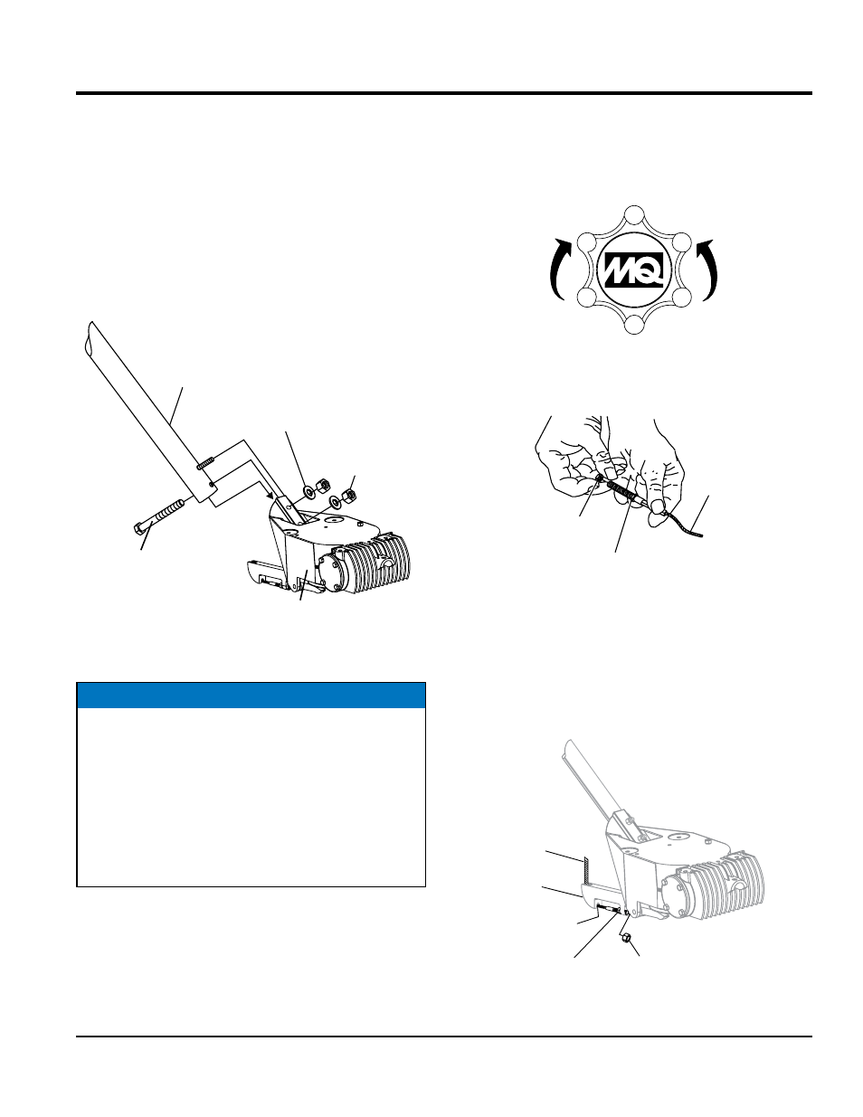
1. Attach the main handle (tube) to the gearbox as shown
in (Figure 4). The mounting hardware should be
contained in the shipping container.
Figure 4. Handle Tube Installation
3/8 FLAT
WASHER
3/8-16
NYLOC NUT
3/8-16 X 3.25
HHC SCREW
MAIN HANDLE
(TUBE)
GEARBOX
NOTICE
If additional handle height adjustment is desired, a
handle wedge kit can be purchased for your trowel by
ordering P/N 2576 from your Multiquip dealer.
These wedges are placed between the handle and the
gearbox to adjust the operating height of the handle.
This kit comes complete with wedges, new bolts and
installation instructions. This will move your operating
handle position up or down approximately 3” (76 mm).
pitch cable installation
1. Expose the pitch cable to maximum by turning the
blade pitch star wheel (Figure 5) fully counterclockwise
for no pitch (blades flat).
Figure 5. Blade Pitch Star wheel
2. Remove brass set nut #1 from the blade pitch cable
end as shown in (Figure 6).
Figure 6. Blade Pitch Cable
3. Thread brass set nut #2 (Figure 6) towards the cable
as far as possible.
4. Insert the cable end through the yoke eyelet
(Figure 7). Tighten brass set nut #1 by hand to remove
all the slack from the cable.
Figure 7. Pitch Cable Yoke Attachment
INCREASE
BLADE PITCH
(CW)
DECREASE
BLADE PITCH
(CCW)
BLADE
PITCH
CABLE
BRASS SET
NUT #1
BRASS SET
NUT #2
BRASS SET
NUT #1
BRASS SET
NUT #2
YOKE
EYELET
YOKE
BLADE
PITCH
CABLE