Multiquip LS-50TD User Manual
Page 22
PAGE 22 — MAYCO LS-40D/LS-40TD/LS-50TD PUMP — OPERATION AND PARTS MANUAL — REV. #11 (09/16/11)
LS-40D/LS-40TD/LS-50TD PUMP — CONTROL BOX COMPONENTS
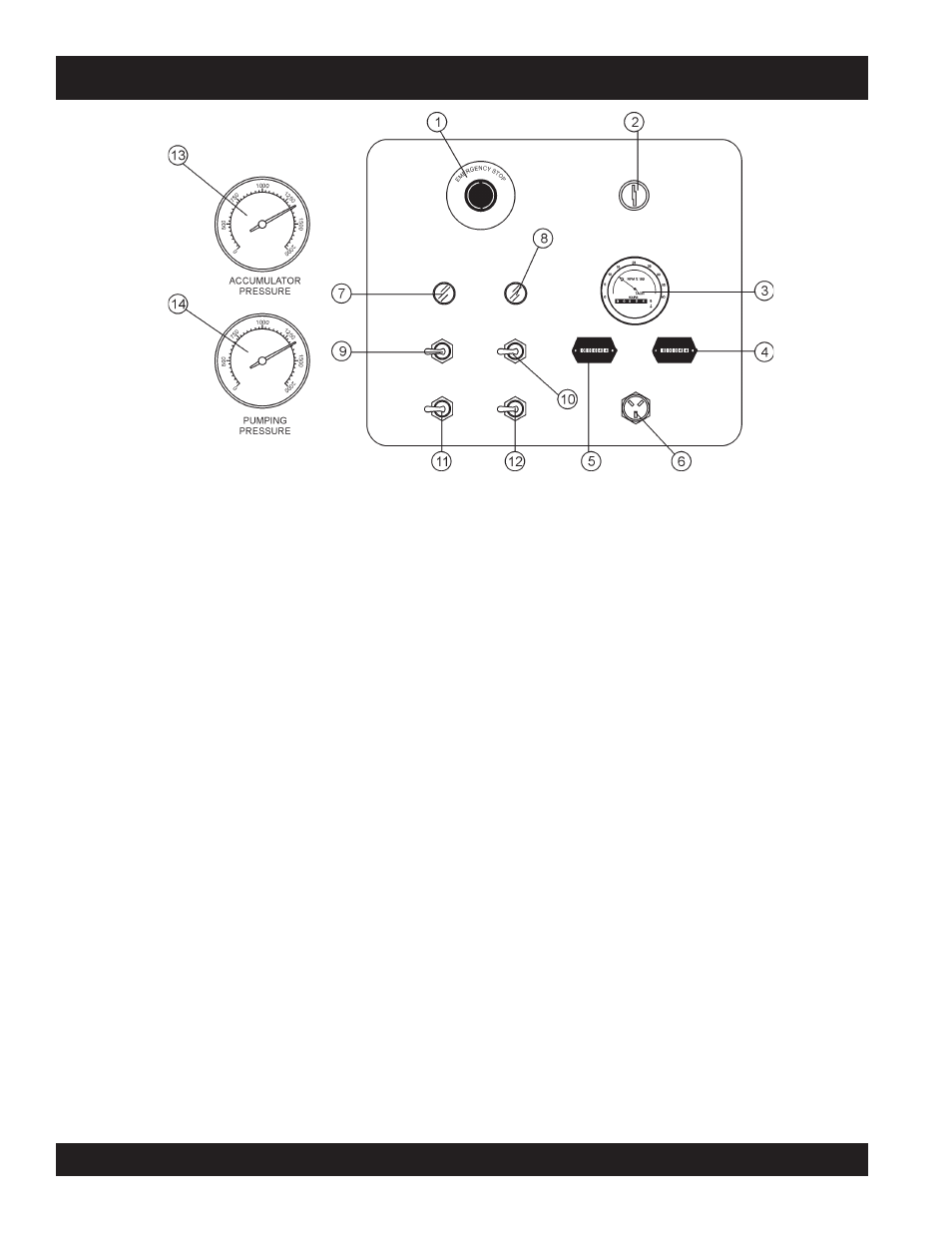
Figure 7. Pump Control Box Components
1.
Emergency Stop Button – Press emergency stop
button to stop pump in an emergency. Turn knob counter
clockwise to disengage the stop button.
2.
Ignition Switch – Insert the ignition key here to start
the engine. Turn the key clockwise to the ON position,
then continue turning clockwise to the START position
and release. To stop the engine turn the key fully counter-
clockwise to the STOP position.
3.
Engine Tachometer – Monitors the engine RPM’s
4.
Engine Hour meter – Display's the number of hours
the engine has been in use.
5.
Pump Hour meter – Display's the number of hours
the pump has been in use.
6.
Remote Cable Connector – Insert the remote control
input cable into this connector.
7.
Battery Indicator Lamp– Indicates a low battery
charge.
Replace or charge battery. NEVER operate the
pump when this lamp is on.
8.
Oil Pressure Indicator Lamp – Indicates incorrect
operational pressure for running the pump. NEVER
operate the pump if this lamp is ON.
9.
Direction Control Switch– This 2 position switch
controls the direction of flow for any mix in the pump.
The
left most position sets the pumping direction to
forward and the
right most position sets the pumping
direction to reverse.
10. Pumping Control Switch – This 3-position switch
controls the pumping of the pump. The
right most
position is for use with the remote control unit, the
left
most position is for normal pumping operation, and the
center most position (OFF) prevents pumping.
11. Cylinder Stroke Control Switch - This three position
switch controls the pumping function. The
left most
position sets the pump to
automatic cycling. Set the
switch to this position for normal pump operation.
The
right most position changes the pump from
automatic to
manual cycling. This allows the cylinders
to be manually cycled using the
Manual Cylinder
Jogging Switch.
12. Manual Cylinder Jogging Switch – This 2 position
switch allows the operator to manually jog the cylinders
to assist in clearing material line packs and is used to
test pumping pressure (See
Initial Start-up Procedure
section of this manual for testing procedure).
The
left most position jogs Cylinder “A” and the right
most position jogs Cylinder “B”.
13. Accumulator Pressure Gauge - This gauge monitors
the system pressure of the Accumulator tank. Normal
system pressure should read approximately 1750 PSI
during pumping.
14. Main Pressure Gauge - This gauge monitors the
system pressure while pumping material. The maximum
pressure rating is 3200 PSI ± 50.