MTS Clip-On Gages User Manual
Page 31
Installation
31
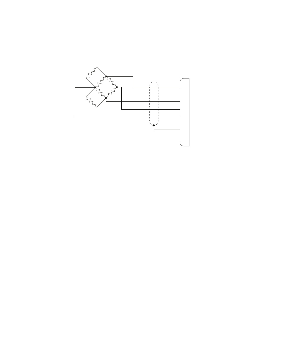
Clip-on Gage Electrical Connections
•
The location of the shunt resistors differs with each controller. See
your controller manual for more information about the shunt
calibration resistors.
•
The location of the bridge balancing circuitry differs with each
controller. See your controller manual for the more information
about the bridge balancing circuitry.
•
The cable attached to the clip-on gage can be from 660–1525 mm
(22–60 in) long. An extension cable or an adaptor cable may be
needed to reach the controller.
1. Attach the plastic connector holder, provided with the clip-on gage,
to the load unit column.
2. Connect the connector, attached to the cable extending from the
clip-on gage, to the mating connector on the appropriate system
cable.
Note
An adapter cable (MTS part number 039-704-601) is available
which allows connection between the PT connector on the clip-
on gage cable and an Amphenol connector on an existing
system cable.
3. Mount the connector assembly in the plastic connector holder.
RED
GRN
BLK
WHT
+Excitation
-Excitation
A
D
C
B
F
E
-Output
+Output
Shield
Shunt
R1
Shunt
R2
1
2
3
4
350
W
Note
The location of the shunt cal
resisters depend on the
controller being used.