MTS Series 685 Hydraulic Grip Supply User Manual
Page 34
Series 685 Grip Supply Product Information
34
Series 685 Grip Supply Controls and Indicators
Operation
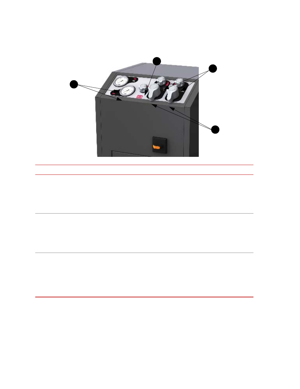
Unless otherwise noted, the controls and indicators are located on the following
control panel figure.
I
TEM
C
ONTROL
D
ESCRIPTION
On/Off
(located on the
front of the Model
685.10 and Model
685.22 chassis)
Applies electrical power to the hydraulic grip supply.
With the switch lever in the On position, power is applied to the unit. When the
pump motor and cooling fan are running, hydraulic pressure is available for
grip operation.
1
Pressure Gages
Show the current hydraulic pressure setting for grip operation. Two gages are
used: one for the upper grip and one for the lower grip.
The gages includes scales for both Bar and psi units.
Use the gages while adjusting the Pressure control to achieve the desired
clamping pressure. See the grip manual for gripping pressures.
2
Rate
Adjusts how fast the grips clamp and unclamp.
Adjust the Rate control clockwise to slow the clamping of the specimen.
Otherwise, adjust the Rate control counterclockwise to increase the clamping
speed.
Important
Different grips require different clamp and unclamp rates; be
sure to adjust the Rate control whenever you change grips.
1
2
3
4