MTS Series 685 Hydraulic Grip Supply User Manual
Page 30
Series 685 Grip Supply Product Information
30
Series 685 Grip Supply Installation Procedure
Installation
If you are installing a Model 685.10 or Model 685.22 Hydraulic Grip Supply,
turn the power switch to the Off position.
1. Position the hydraulic grip supply.
Locate the grip supply close to the load unit so that you can reach both grips
(for specimen installation) and you can operate the hydraulic grip supply.
If it is not possible to do this due to the size of the load unit or other physical
reasons, position the hydraulic grip supply to provide the maximum
convenience.
Be sure to connect hoses to the correct ports.
Connecting hoses to the wrong ports can cause unexpected grip movement and
equipment damage.
2. Connect the hydraulics.
A.
Remove the caps from the four ports on the rear of the hydraulic grip
supply and connect hydraulic hoses.
B.
Connect the other ends of the hydraulic hoses to the corresponding
fittings on the upper and lower grips.
The remaining steps apply
only to the Model 685.10
and Model 685.22
Hydraulic Grip Supplies.
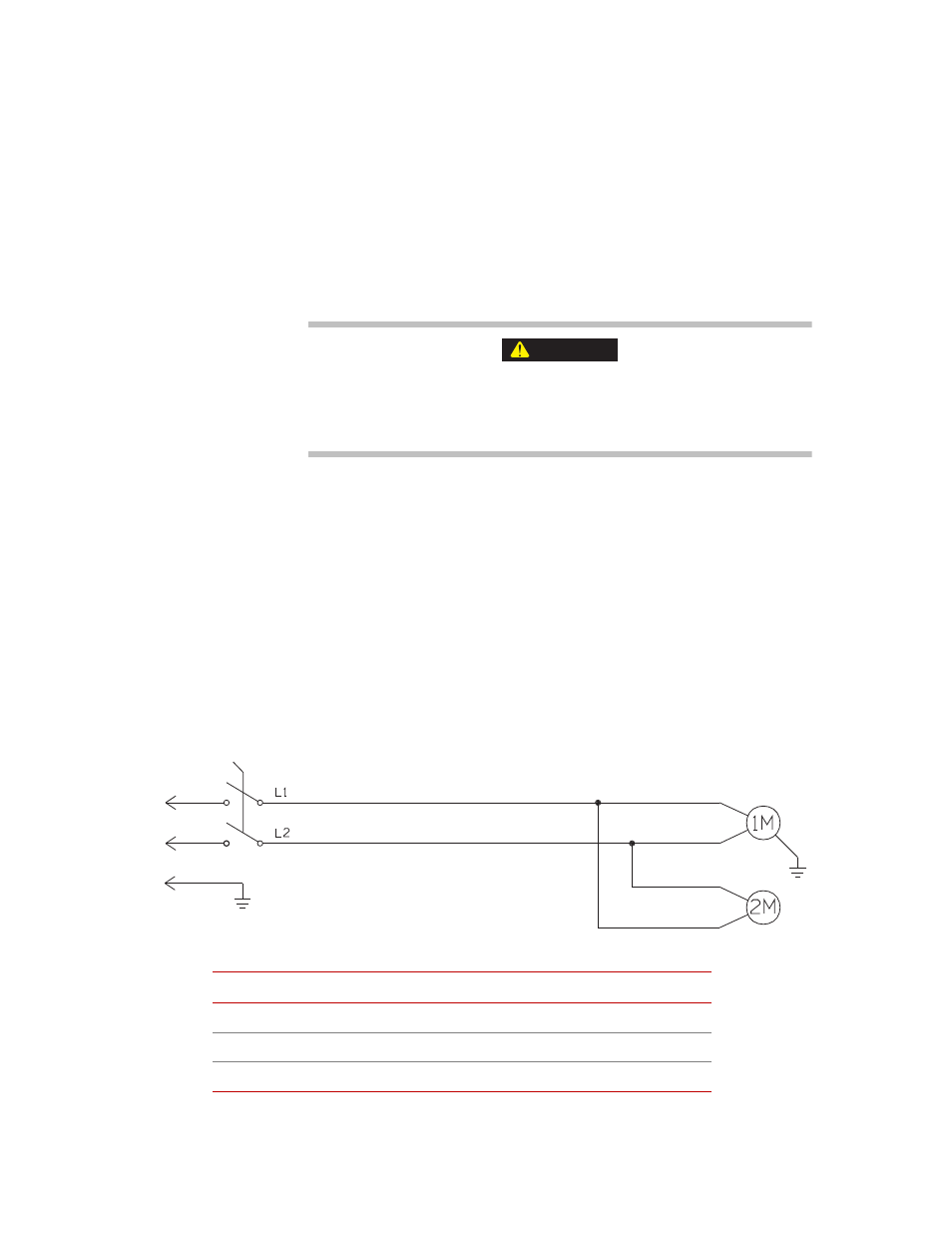
3. Configure the power connection.
The appropriate connector for your local service should be included with the
hydraulic grip supply. If the power cord is not connected, use the following
figure to assist you in connecting the power cord.
Plug the unit power cord into the appropriate power source.
CAUTION
C
USTOMER
-S
UPPLIED
P
OWER
L1
L2
115 V / 60 Hz / 1 phase
115 V
Common
208 V/ 60 Hz / 1 phase
104 V
104 V
230 V / 60 Hz / 1 phase
115 V
115 V
Cooling Fan Motor
Hydraulic Pump Motor
On/Off Switch
Ground
Note: All local codes override
the wiring diagram and
matrix table.