Series 685 grip supply installation procedure, Series 685 grip supply installation procedure 29 – MTS Series 685 Hydraulic Grip Supply User Manual
Page 29
Series 685 Grip Supply Installation Procedure
Series 685 Grip Supply Product Information
Installation
29
4. Move the grip supply.
The grip supply can be moved on its pallet with a fork lift or it can be
moved with its lifting hoist rings.
Lift the grip supply only as high as necessary, and move it slowly to the
installation site.
5. Remove the chains/slings.
6. If necessary, secure the grip supply.
The grip supply can be secured to an adequate foundation. The base of the
grip supply has a hole in each corner; diameter 13.48 mm (0.531 in). Refer
to the drawings for spacing requirements.
7. Contact MTS Systems Corporation to arrange for installation services.
In the U.S. and Canada, call the MTS Call Center at 1-800-328-2255.
Elsewhere, contact your local MTS office.
Series 685 Grip Supply Installation Procedure
Under-rated hoses can rupture.
Ruptured hoses can cause injury to personnel or damage to equipment.
Do not use hydraulic hoses rated for less than 69 MPa (10,000 psi) for the 685.10
and 685.60 or 21 MPa (3000 psi) for the 685.22. Use only hydraulic hoses that
have a working pressure greater than 69 MPa (10,000 psi).
WARNING
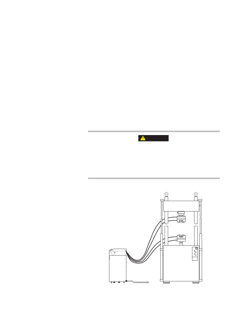
Each
connection
is labeled
This illustration shows the
connections you need to make
when you install the hydraulic
grip supply.