4 emc interference injections, Emc interference injections – Lenze Inverter EMC User Manual
Page 9
EMC interference injections
7
l
EDBEMV EN 1.3
4
EMC interference injections
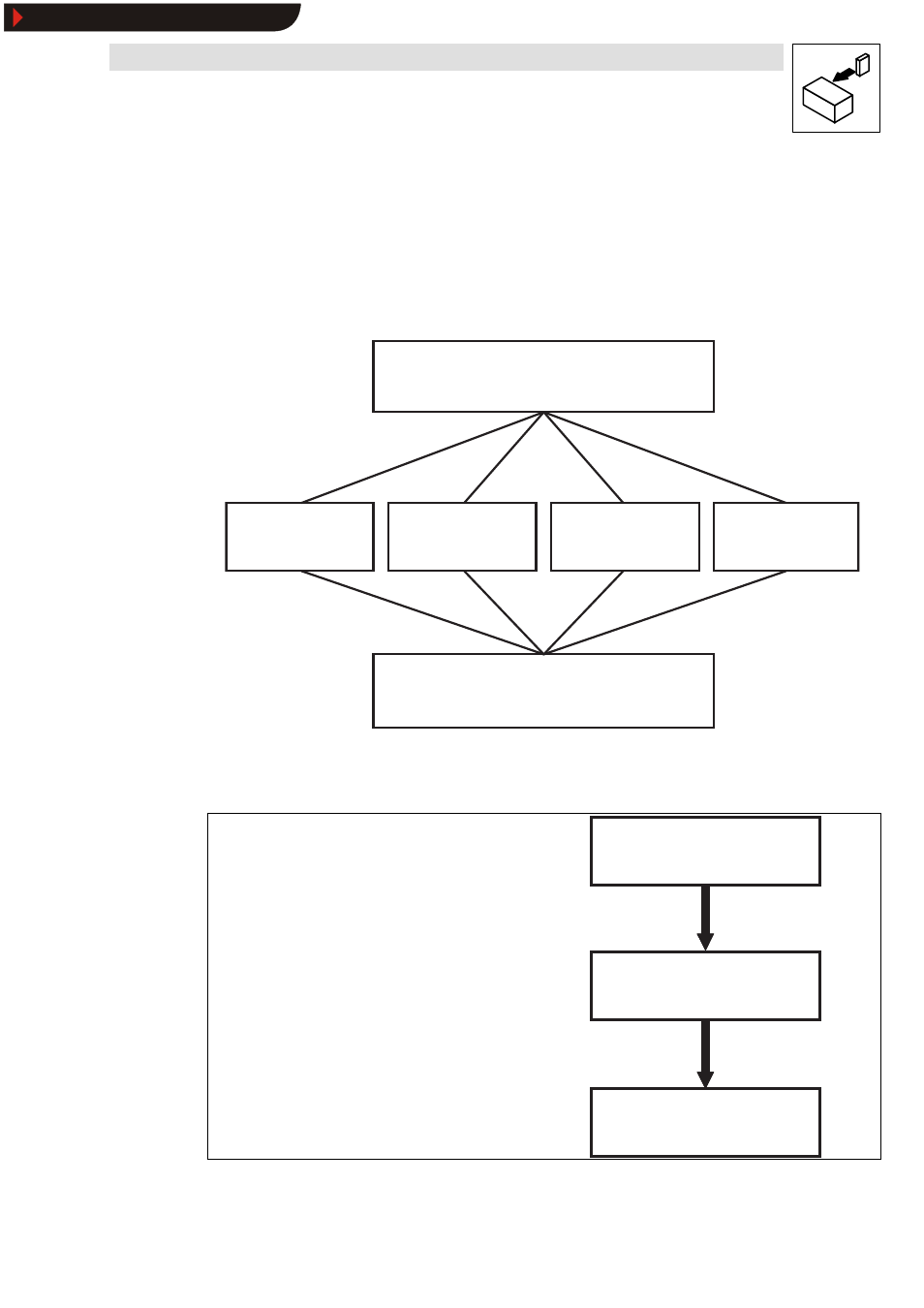
The injection of EMC interference is characterised by different coupling mechanisms. The
respective coupling mechanism is the “ transmission path“ between interference source and
potentially susceptible equipment.
There are 4 different coupling mechanisms:
E l e c t r o m a g n e t i c e n v i r o n m e n t
( i n t e r f e r e n c e s o u r c e )
R e c e i v e r ( p o t e n t i a l l y
s u s c e p t i b l e e q u i p m e n t )
C o n d u c t i v e
c o u p l i n g
C a p a c i t i v e
c o u p l i n g
I n d u c t i v e
c o u p l i n g
R a d i a n t
c o u p l i n g *
*
Combination of capacitive and inductive coupling
Fig. 4
EMC: Coupling mechanisms
The degree of intensity of the interference injection may be reduced by various different measures:
At the transmitter
•
Shielding
•
Filters
I n t e r f e r e n c e s o u r c e
( e m i t t e r )
P o t e n t i a l l y s u s c e p t i b l e
e q u i p m e n t ( r e c e i v e r )
C o u p l i n g m e c h a n i s m
( p a t h )
At the coupling mechanism
•
Shielding
•
Topology
•
Optical waveguide (electrical isolation)
I n t e r f e r e n c e s o u r c e
( e m i t t e r )
P o t e n t i a l l y s u s c e p t i b l e
e q u i p m e n t ( r e c e i v e r )
C o u p l i n g m e c h a n i s m
( p a t h )
At the receiver
•
Shielding
•
Filters
•
Circuitry arrangement
I n t e r f e r e n c e s o u r c e
( e m i t t e r )
P o t e n t i a l l y s u s c e p t i b l e
e q u i p m e n t ( r e c e i v e r )
C o u p l i n g m e c h a n i s m
( p a t h )
Show/Hide Bookmarks