3 interference range of frequency inverters, Interference range of frequency inverters, Interference ranges for frequency inverters – Lenze Inverter EMC User Manual
Page 8: 3interference range of frequency inverters
Interference ranges for frequency inverters
6
l
EDBEMV EN 1.3
3
Interference range of frequency inverters
Overview - frequency inverter interference ranges
Mains current harmonics
Interference emission
Conducted
Conducted
Non-conducted (interference)
Frequency range
0 ... 2.5 m
150 kHz ... 30 MHz
30 MHz ... 1 GHz
Cause
Non-sinusoidal mains current
High-speed switching of output
stages and switched-mode power
supplies. Their electrical
connection results in interference
injection to the mains input.
The switching edges of output stages
with high rate of voltage rise include
high-frequency harmonics that, as
”transmitters”, emit interferences in
connection with the motor cables
(aerials).
Effect
•
Increased eff. mains current
•
Additional temperature rise in
mains supply transformers
Interference injection on the
mains side into other
consumers on the same mains
(electrical connection)
Interfering radiation of inverter and motor
cable to other nearby high-resistance
control signal cables
Countermeasures
•
Mains choke
•
PFC (Power-Factor-Correction)
RFI filter on the mains side
(internal / external)
•
Shielding of inverter and motor cable
•
Continuous shield
•
Optimum shield connection
•
Short unshielded wire ends
Standards for limit class
A (industrial)
EN 61800-3
EN 55011
EN 55011
Standards for limit class
B (residential)
EN 61000-3-2: Electrical
equipment
•
Mains current < 16 A or
•
Input power < 1 kW
EN 55022
EN 55022
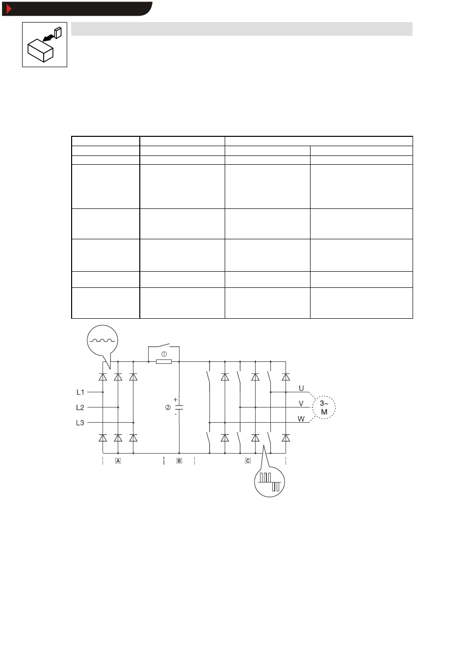
Fig. 3
Power unit of the DC bus inverter
Uncontrolled input rectifier
DC bus
Three-phase inverter
c
Power-on protection
d
DC bus capacitors
Show/Hide Bookmarks