9 equipotential bonding, Equipotential bonding, 9equipotential bonding – Lenze Inverter EMC User Manual
Page 20
Equipotential bonding
18
L
EDBEMV EN 1.3
9
Equipotential bonding
Potential differences occur in:
z
Spatially separate mounting plates within a control cabinet
z
Several control cabinets spatially distributed within the system
z
Use of decentralised controllers (motec/starttec)
z
Components fed from different supplies
Existing potential differences cause a flow of compensating currents which amount up to several
amperes for short periods.
The effects of potential differences are as follows:
z
Interference of control signals
z
Interference of communication systems (error frames)
z
Destruction of electronic components (e.g. interfaces)
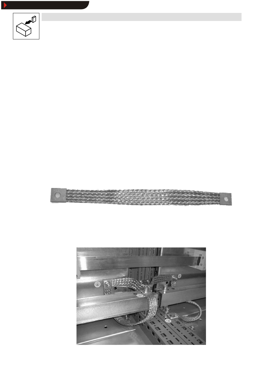
The following measures are suitable to reduce potential differences:
z
Establish equipotential bonding between mounting plates/control cabinets with the help of
large-surface large-contact earthing strip.
Fig. 10
Earthing strip for equipotential bonding
z
Set up supplies with joint reference potential
z
Provide large-surface shield contact surfaces
z
Provide an electrical isolation (optical or isolating transformer) if above measures do not
suffice.
Fig. 11
Improving the shielding effect inside the control cabinet
Show/Hide Bookmarks