1 conductive coupling, 2 capacitive coupling, 3 inductive coupling – Lenze Inverter EMC User Manual
Page 10: Conductive coupling, Capacitive coupling, Inductive coupling, Emc interference injections, Ucircuit 2 circuit 1 coupling inductance i
EMC interference injections
8
l
EDBEMV EN 1.3
4.1
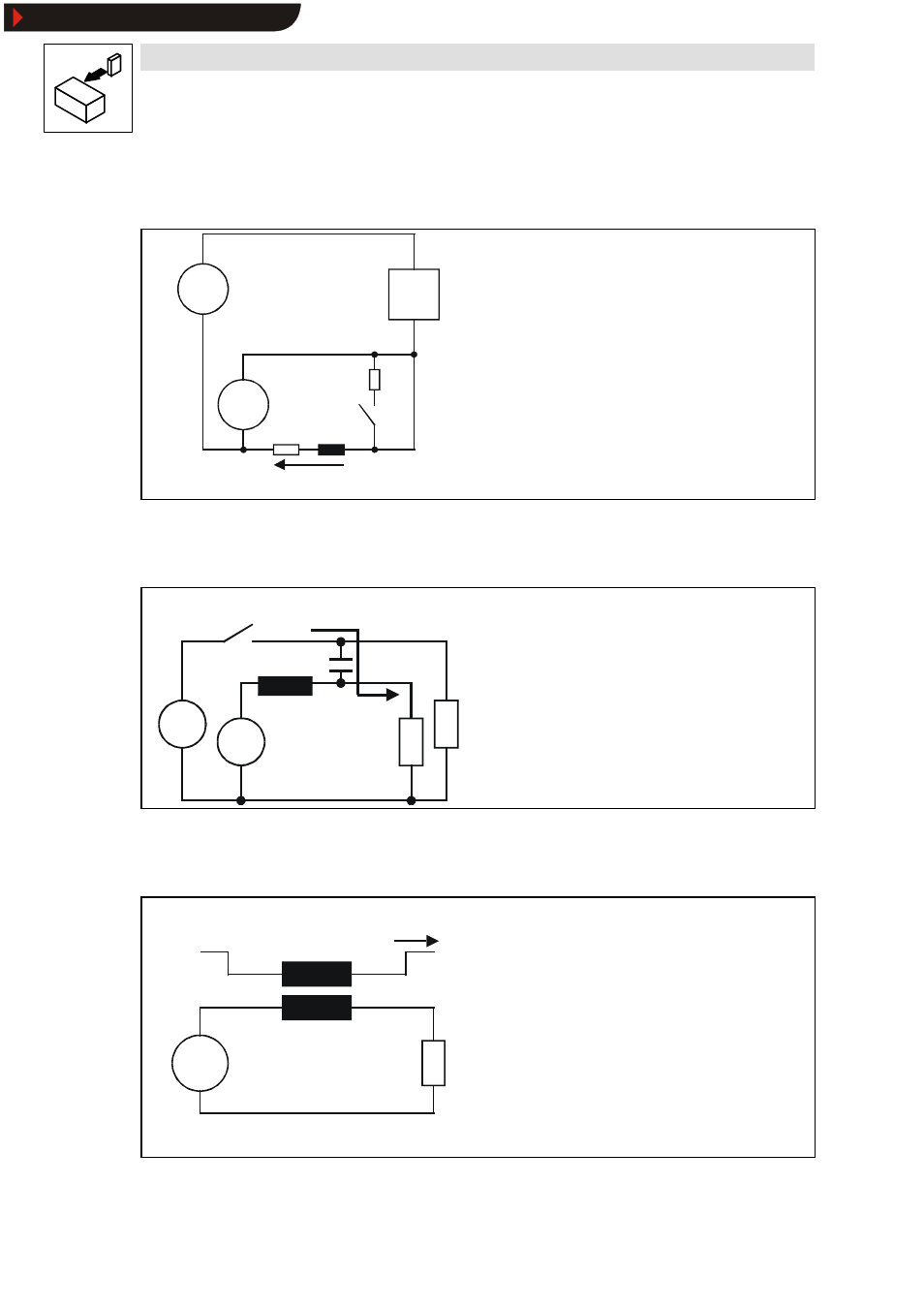
Conductive coupling
U2
U1
PLC
Interference voltage
Conductive coupling is the result of several power circuits using the
same line sections.
Causes
•
Frame and earth connections
•
Coupling of various power circuits
•
Earth loops
Countermeasures
•
Short joint reference conductors
•
Electrical isolation of the systems (transformer, relays ... )
4.2
Capacitive coupling
U1
Coupling current
U2
Capacitive coupling occurs due to the impact of electrical fields on
adjacent cables.
Causes
•
High- voltage / signal cables
•
Switching of inductances
•
Parallel cable arrangement
Countermeasures
•
Increase distance between cables
•
Reduce parallel cable length
•
Shield cables
•
Reduce rate of voltage rise
4.3
Inductive coupling
U
Circuit 2
Circuit 1
Coupling inductance
I
Inductive coupling occurs due to the impact of magnetic fields on
adjacent cables.
Causes
•
High-voltage current switching
•
Switching of capacitances
•
Parallel cable arrangement
Countermeasures
•
Increase distance between cables
•
Reduce parallel cable length
•
Twist forward and return conductors
•
Reduce rate of current rise
Show/Hide Bookmarks