5 installing the cables within the control cabinet, Installing the cables within the control cabinet, Arrangement according to emc requirements – Lenze Inverter EMC User Manual
Page 15
Arrangement according to EMC requirements
13
l
EDBEMV EN 1.3
6.2.5
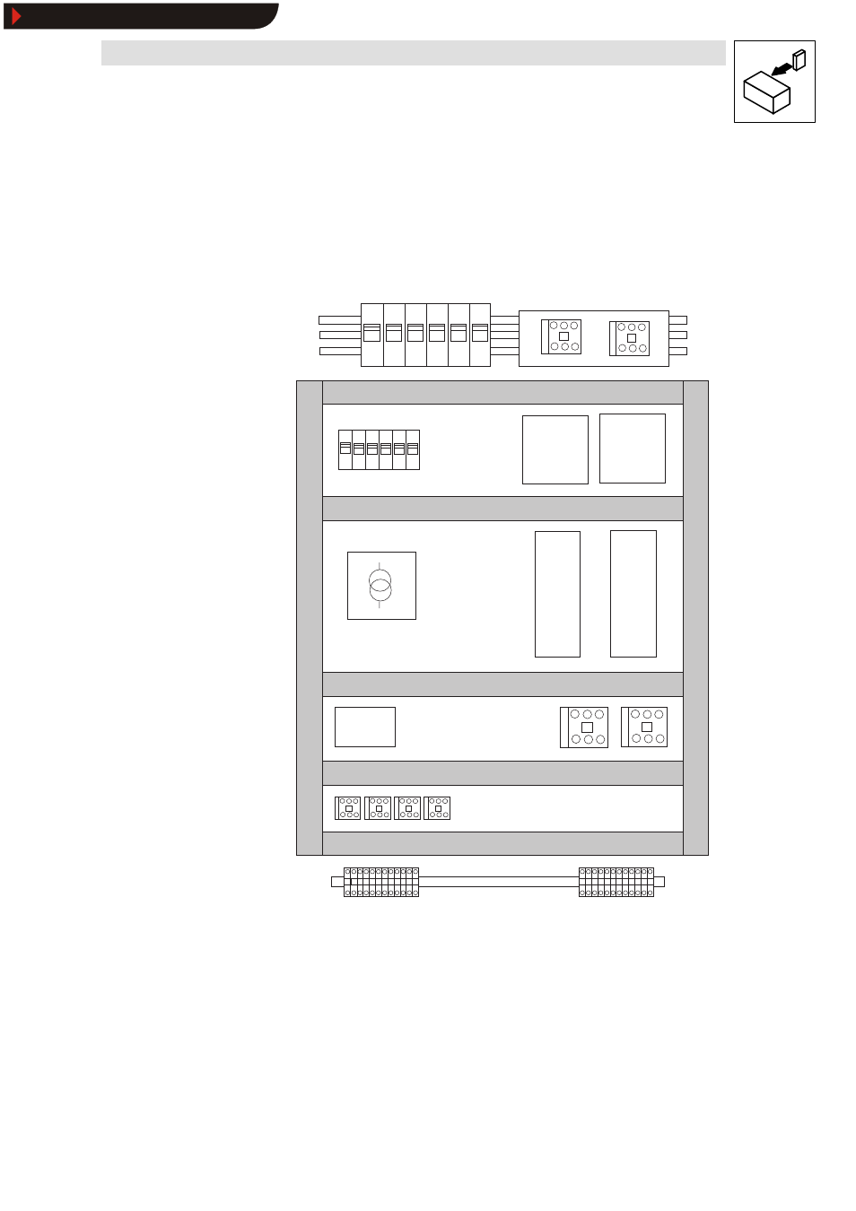
Installing the cables within the control cabinet
Separation of the “ hot” motor cable from control cables, signal cables and mains cables:
z
Never install motor and signal cables in parallel. Crossings must be laid at right angles.
z
Arrange the conductors of a 24 V power supply unit close together along the whole length so
that no loops may occur.
Filters on
mains side
Filters on
mains side
8200
vector
8200
vector
PLC
Mains fuses
Mains contactors
Fuses
24V power supply unit
Motor
contactors
Relay
Connection terminals
Cable
duct
for
signal
and
mains
cables
Cable
duct
for
motor
cables
Fig. 7
Cable routing in the control cabinet
Show/Hide Bookmarks
See also other documents in the category Lenze Hardware:
- ESMD smd tmd remote keypad (4 pages)
- EPM Programmer EEPM1RA (114 pages)
- ESMDC (36 pages)
- SMD Frequency Inverter 0.37kW-22kW (116 pages)
- SMD Frequency Inverter: Basic I/O with CANopen 0.25kW-4.0kW (36 pages)
- SMD 0-25kW-4-0kW (112 pages)
- smd Series Drives (32 pages)
- ESV SMV remote keypad H0 (2 pages)
- ESV SMV remote keypad H1 (2 pages)
- SV SMV additional I-O module (14 pages)
- EEPM1RA EPM (26 pages)
- SMVector RS-485 LECOM (29 pages)
- E84AYM10S (4 pages)
- E84AYCET EtherCAT MCI module (109 pages)
- EZAMBKBM (6 pages)
- E84AYCEC (89 pages)
- ERBPxxxRxxxx Brake resistor 200W-300W (134 pages)
- E84AYCPM (115 pages)
- E84AYCEO (165 pages)
- E84AYCER (94 pages)
- E84AVSCx 8400 StateLine C (76 pages)
- EZVxxxx-000 Power supply unit AC 230V 5A-20A (62 pages)
- E84AYCIB (75 pages)
- E82ZWBRB (48 pages)
- EZVxx00−001 Power supply unit AC 400V 5A-20A (64 pages)
- E82ZWBRE (64 pages)
- EZAEBK1001 (94 pages)
- E94AYAE SM301 (74 pages)
- E94AYAE SM301 (140 pages)
- E94AYAE SM301 (134 pages)
- E94AZPS (114 pages)
- E94AYCIB (78 pages)
- E94AYCIB (124 pages)
- E94AZEX100 (84 pages)
- EZS3-xxxA200 Sinusoidal filter 115-150A (44 pages)
- E94AZHA0051 (104 pages)
- E94AZCDM030 (72 pages)
- EZS3-xxxA200 Sinusoidal filter 180-480A (74 pages)
- E94AYCCA (188 pages)
- E94AYCCA (114 pages)
- E94AZHB0101 (104 pages)
- E94AYCPM (125 pages)
- E94AYCPM (114 pages)
- E94AYCET (140 pages)
- E94AYCET (103 pages)