Codes 8, C1510: configuration of process input data – Lenze E82ZAFVC010 User Manual
Page 41
Codes
l
41
EDS82ZAFVCxxx EN 4.0
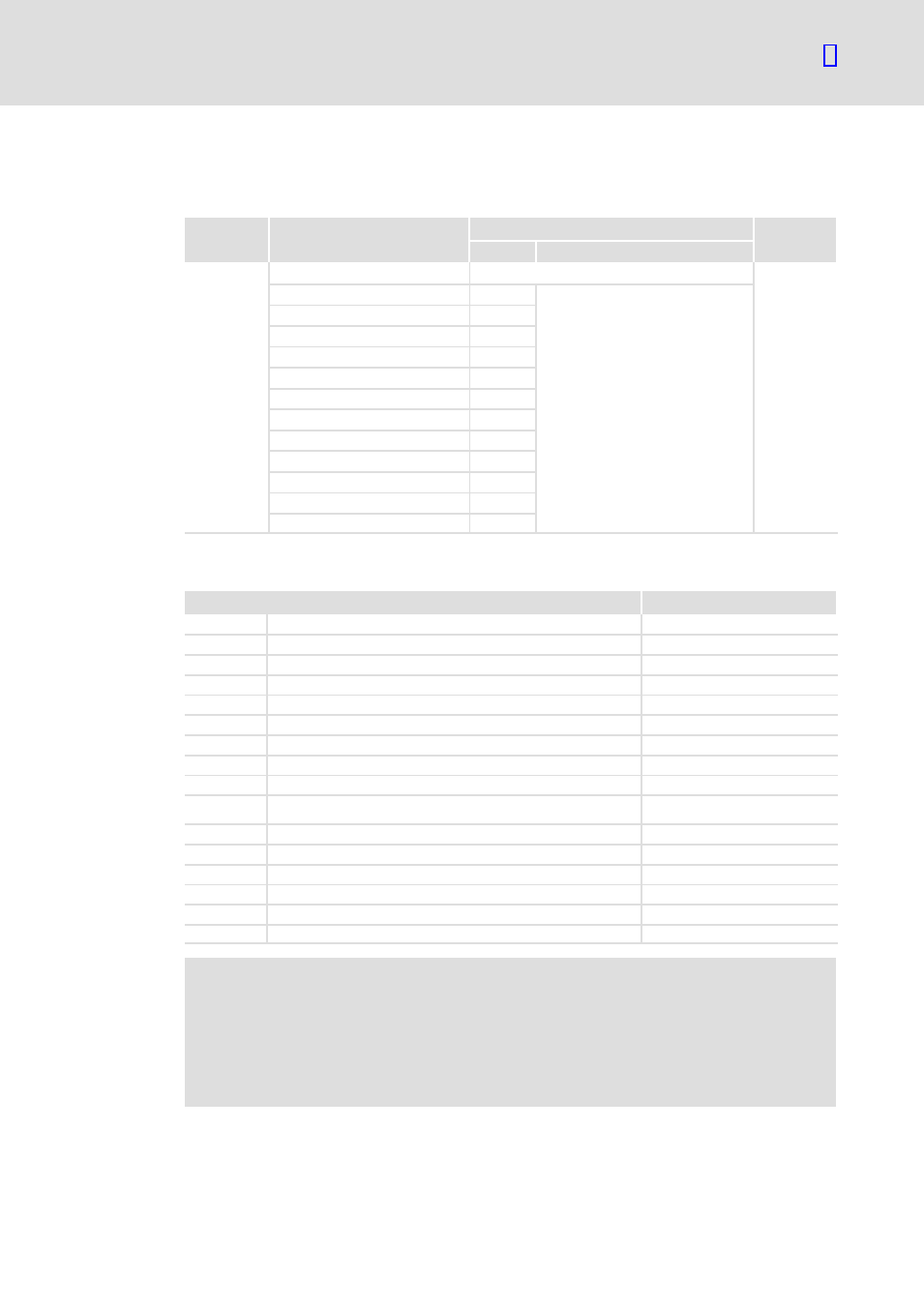
C1510:
Configuration of process input data
Code
Subcode
Possible settings
Data type
Lenze
Selection
C1510
FIX32
1 (PEW1)
1
See table below
2 (PEW2)
3
3 (PEW3)
4
4 (PEW 4)
5
5 (PEW 5)
6
6 (PEW 6)
7
7 (PEW 7)
8
8 (PEW 8)
9
9 (PEW 9)
10
10 (PEW 10)
11
11 (PEW11)
12
12 (PEW12)
13
The assignment of the bit status information or the actual values of the controller to the
max. 12 process data input words (PEW) of the master can be freely configured.
Selection
Scaling
1
FIF status word 1 (FIF−STAT1)
16 bits
2
FIF status word 2 (FIF−STAT2)
16 bits
3
Output frequency with slip (MCTRL1−NOUT+SLIP)
±24000
º ±480 Hz
4
Output frequency without slip (MCTRL1−NOUT)
±24000
º ±480 Hz
5
Apparent motor current (MCTRL1−IMOT)
2
14
º 100 % rated device current
6
Actual process controller value (PCTRL1−ACT)
±24000
º ±480 Hz
7
Process controller setpoint (PCTRL1−SET)
±24000
º ±480 Hz
8
Process controller output (PCTRL1−OUT)
±24000
º ±480 Hz
9
Controller load (MCTRL1−MOUT)
±2
14
º ±100 % rated motor torque
10
DC−bus voltage (MCTRL1−DCVOLT)
16383
º 565 VDC at 400 V mains
16383
º 325 VDC at 230 V mains
11
Ramp function generator input (NSET1−RFG1−IN)
±24000
º ±480 Hz
12
Ramp function generator output (NSET1−NOUT)
±24000
º ±480 Hz
13
FIF−OUT.W1
16 bits or 0 ... 65535
14
FIF−OUT.W2
16 bits or 0 ... 65535
15
FIF−OUT.W3
0 ... 65535
16
FIF−OUT.W4
0 ... 65535
)
Note!
ƒ
FIF−OUT.W1 is digitally defined in the Lenze setting and assigned with the
16 bits of the controller status word 1 (C0417).
ƒ
Before you assign an analog signal source (C0421/3
¹ 255), the digital
assignment must be deleted (C0417/x = 255)! Otherwise the output signal
would be incorrect.