Electrical installation – Lenze DISCO−Variable speed drive User Manual
Page 22
Electrical installation
Electrical adjusting device
Operational check
l
22
BA 11.5032−EN 3.0
4. The adjustment motor and actuator must stop.
5. If the actuator and adjustment motor do not stop, reverse the polarity of the
adjustment motor.
Adjustment motor in position 3 / limit−switch box in position 5
1. Switch on the DISCO.
2. Increase the speed: clockwise rotation of the actuator in the limit−switch housing.
3. While the speed is increased, activate the limit−switch S3 with an insulated
screwdriver.
4. The adjustment motor and actuator must stop.
5. If the actuator and adjustment motor do not stop, reverse the polarity of the
adjustment motor.
Adjustment motor in position 5 / limit−switch in position 3
Adjustment motor in position 3 / limit−switch in position 5
GT−DISCO−003.iso
GT−DISCO−004.iso
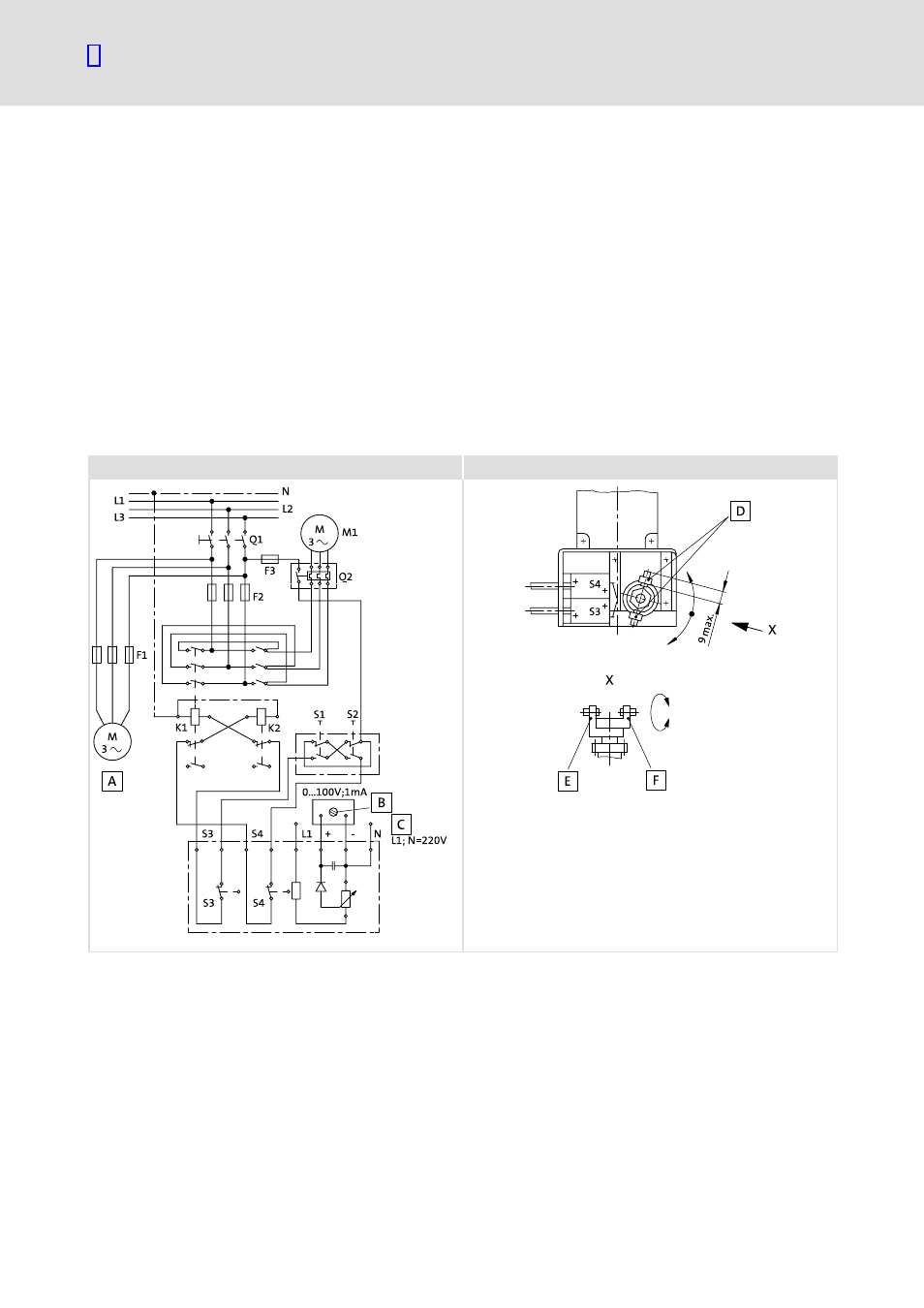
Fig. 2
Circuit plan of the servo adjustment mechanism with potentiometer indicator
0 Driving motor
3 Actuator (the long lever activates S3)
1 Adjustable
4 Long lever
2 Auxiliary supply L1, N=230 V~
5 Short lever
A1
Indicator 0...100V =/ 1000
W/V
(option)
Q1
Main switch*
F1, F2, F3
Fuses*
Q2
Motor protection switch*
K1, K2
Reversing contactors*
S1, S2
Pushbutton switches*
M1
Adjustment motor
S3, S4
Limit switches
* not included in the scope of supply