Overview – Lenze E94AMHE User Manual
Page 46
l
46
EDK94AMH24 DE/EN/FR/ES/IT 3.1
Overview
Standard device
0
Design
Pos.
Description
HighLine
StateLine
MXI1
Module receptacle for extension 1, e.g. communication
ю
ю
MXI2
Module receptacle for extension 2, e.g. communication
þ
o
MMI
Module receptacle for memory modules
ю
ю
MSI
Module receptacle for safety modules
ю
ю
X1
System bus (CAN), under the cover
þ
o
X2
24−V supply and state bus
ю
ю
X3
Analog inputs and analog outputs
2/2
1/0
X4
Digital outputs
4
1
X5
Digital inputs
8
4
X6
Diagnostics
ю
ю
X7
Resolver
ю
ю
X8
Encoder
ю
ю
2
Lower cap
ю
ю
3
Nameplate, retractable
ю
ю
4
Upper cap
ю
ю
8
EMC clamp
1
1
:
Warning sticker − place close to the device in a clearly visible manner!
ю
ю
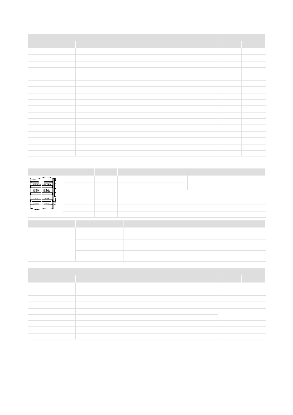
The LED display enables fast indication of several operating states.
LED
Labelling
Colour
Description
CAN−RUN
green
CAN bus o.k.
Inoperable when "StateLine" design is
used
CAN−ERR
red
CAN bus error
DRIVE READY
green
Standard device is ready for operation
DRIVE ERROR
red
Error in the standard device or due to the application
24 V
green
24−V supply voltage o.k.
SSP94LED01
USER
yellow
Message parameterised by the application
Pos.
Symbol
Description
5
{
Long discharge time: All power terminals carry hazardous voltages for at
least 3 minutes after mains disconnection!
}
High discharge current: Fixed installation and PE connection to EN 61800−5−1
required!
'
Electrostatic sensitive devices: Before working on the device, personnel must
ensure that they are free of electrostatic charge!
Installation backplane
1
Design
Pos.
Description
HighLine
StateLine
X100
DC−bus voltage (compatible to 9300 series)
þ
X105
Motor
þ
X106
Motor temperature monitoring
þ
X107
Control of motor holding brake
Optional
X109
DC busbar +
þ
X110
DC busbar −
6
EMC wire clamp (for device sizes 2 + 3), replaces 1x
7
1
7
EMC shield clamp
3 or 2
;
DC−bus fuse
þ
0Fig. 0Tab. 0