Connecting the supply and peripheral devices, Terminal diagram supply, 24 v connection (x101) – Lenze CPC 2800 Operating Instructions User Manual
Page 29: Electrical installation
Electrical installation
Connecting the supply and peripheral devices
Terminal diagram supply
l
29
BA_CPCx8xx EN 3.0
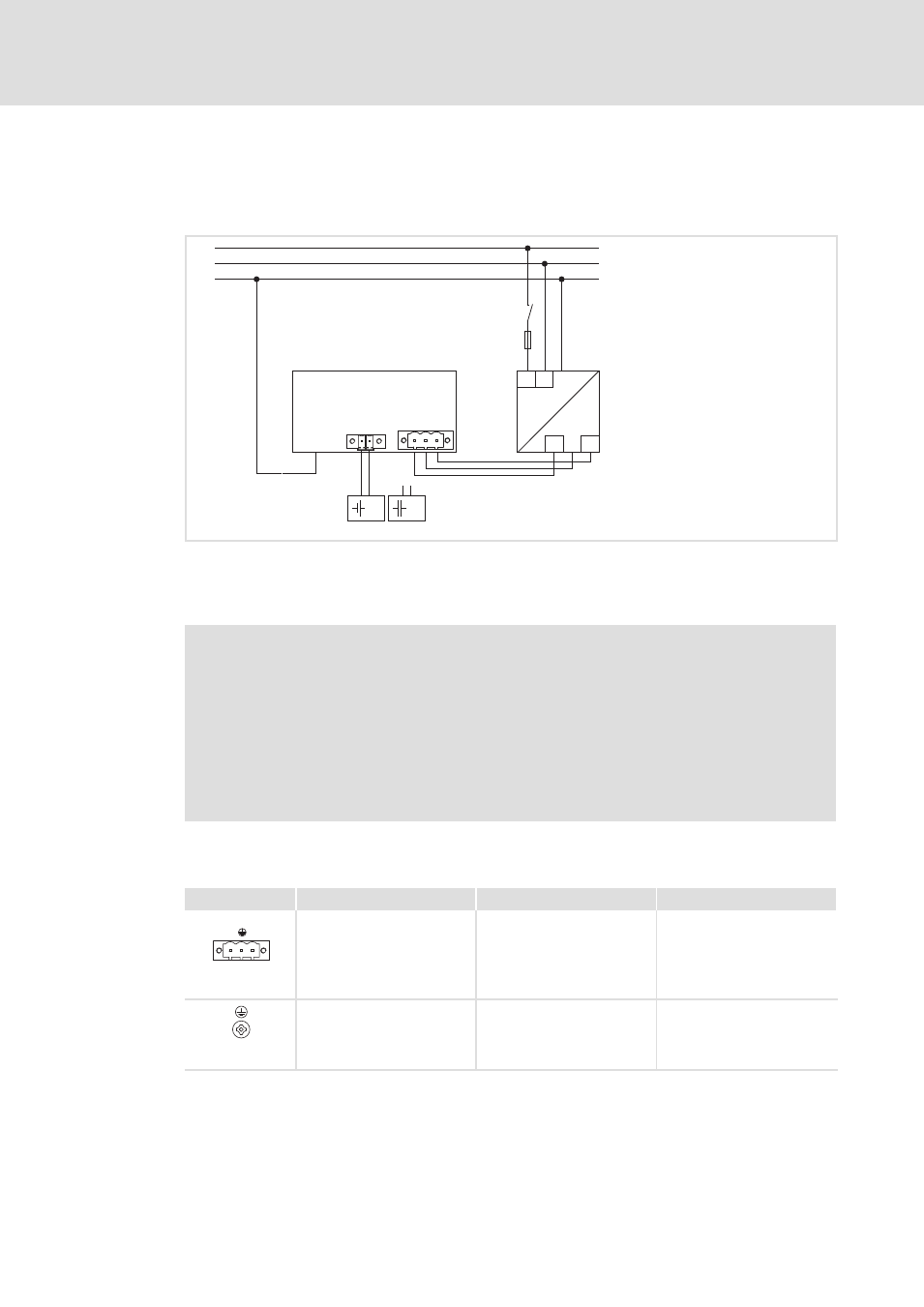
6.3
Connecting the supply and peripheral devices
6.3.1
Terminal diagram supply
L1
N
PE
L1 N
+
0V
+24
+
~
=
0 V
USV
PE +24 V
+
0
1
2
3
F
S
Elx7xx−006
0
IPC
1
Power supply unit
2
Battery pack (Option)
3
Capacitor pack (Option)
)
Note!
ƒ
Observe the max. permissible input voltage.
Professionally fuse the device on the input side against voltage fluctuations
and voltage peaks.
ƒ
The IPC boots up as soon as the supply voltage is applied.
After the operating system has been shut down, the IPC switches off
automatically. For restarting, the supply voltage has to be disconnected for a
short time.
6.3.2
24 V connection (X101)
Description
Connection type
Cable type
0V
U
DC 24 V connection
3−pole Phoenix Combicon
socket
Cable (conductor
cross−section max. 2.5 mm
2
)
with Phoenix Combicon plug,
MSTB 2.5 / 3−STF−5.08
IPC001
PE connection
M4 Recessed head screw
Separate earthing conductor
(min. 2.5 mm
2
) with ring
cable lug
IPC001