Electrical installation – Lenze CS9800 Operating Instructions User Manual
Page 46
Electrical installation
Assignment of the operator console connector board (only CS 5810)
l
46
BA_CSx8xx EN 3.0
6.4
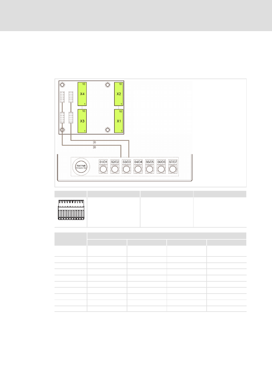
Assignment of the operator console connector board (only CS 5810)
The adapter board is located within the mounting frame of the Command Station. The
scope of supply includes four connector plugs that are plugged on the basic housings of the
adapter board in position X1 to X4.
CSB−006
Description
Connection type
Cable type
Connections for wiring the
control/display elements of
the control desk
10−pole Phoenix Combicon
socket with spring pressure
connection, type FK−MC
0.5/10−ST−2.5
Flexible due to wire end
ferrule, conductor
cross−section 0.14 ... 0.5 mm
2
CSB−008
Contact
Assignment
X1
X2
X3
x4
1
Key voltage S1 ... S7
(e. g. +24 V)
LED−GND (LED 1 ... 7)
Key voltage S1 ... S7
(e. g. +24 V)
N.C.
2
S 1.1
LED D1 anode
S 1.2
N.C.
3
S 2.1
LED D2 anode
S 2.2
N.C.
4
S 3.1
LED D3 anode
S 3.2
N.C.
5
S 4.1
LED D4 anode
S 4.2
N.C.
6
S 5.1
LED D5 anode
S 5.2
N.C.
7
S 6.1
LED D6 anode
S 6.2
N.C.
8
S 7.1
LED D7 anode
S 7.2
N.C.
9
Emergency stop 1.1
Emergency stop 2.1
Potential I: S1/S5
Potential III: S3/S7
10
Emergency stop 1.2
Emergency stop 2.2
Potential II: S2/S6
Potential IV: S4