Mechanical installation – Lenze CS9800 Operating Instructions User Manual
Page 37
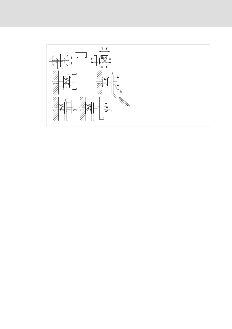
Mechanical installation
Mounting steps
Fixing the mounting frame to the wall
l
37
BA_CSx8xx EN 3.0
With add−on component
29.
5
10
6
70
160
2
1
6
0
0
2
3
3
4
5
1
4
3
4
CS57x0−011
How to proceed:
1. Prepare the wall for mounting the wall bracket
0.
– The mounting location and the installation material must provide for a permanent
mechanical connection.
2. Stick the self−adhesive seal
1 on the adapter plate 2 on the side with the threaded
bolts.
3. Screw the wall bracket
0 and the adapter plate 2 to the swivel adapter 3.
– 2 x 4 countersunk head screws M5 x 16 mm with washers
Æ 5.3 mm and nuts M5
4. Pull the connecting cable through the swivel adapter
3 and screw the swivel
adapter to the wall.
5. Screw the add−on component
4 to the threaded bolts of the swivel adapter 3.
– 4 spacer bolts
5 on the inside/outside M5 x 20 mm
6. Stick the second self−adhesive seal
1 on the add−on component 4.
7. Screw the mounting frame
6 to the add−on component 4.
– 4 nuts M5 with washers
Æ 5.3 mm
– 4 screws M5 x 8 mm with washers
Æ 5.3 mm
Now you can connect the Command Station (
¶ 39).