Hydraulic layout – Landoll HCDA73-1 Soil Builder Coulter Chisel User Manual
Page 22
2-12
2J757
ASSEMBLY
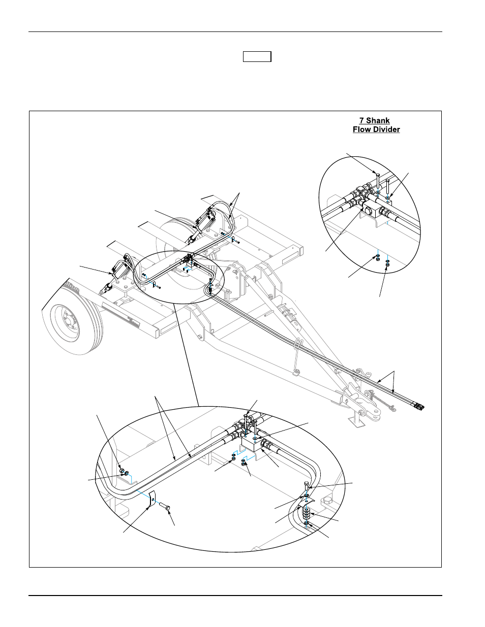
Hydraulic Layout
Install hydraulic components as shown; See
Figures 2-13, 2-14. Use the shorter hoses on the right
side of the machine. For hydraulic fittings torque values,
See Page 4-2.
NOTE
The hoses from the Flow Divider Valve must be
connected to the rod end of the cylinders.
Figure 2-13: Hydraulic Layout (5 Shank Shown, 7 Shank Similar)
CD HydLayout5Shank
Hose Assm
3/8 x 161”
3 x 8
Hyd Cyl
3 x 8
Hyd Cyl
Hose Assm,3/8 x 50”
5 Shank
Hose Assm,3/8 x 72”
7 Shank
Flat Washer,
1/4”
Flat Washer,3/8”
Lock Washer,3/8”
Clamp
Lock
Washer,3/8”
Hose Assm
3/8 x 50
Lock Washer,3/8”
Nut,3/8-16
Clamp
HHCS,
3/8-16 x 1-1/2”
HHCS,
3/8-16 x 1”
Nut,1/4-20
Flow
Divider
Lock
Washer,1/4”
HHCS,
1/4-20 x 2”
Nut,1/4-20
Lock
Washer,1/4”
Flow
Divider
HHCS,
1/4-20 x 2”
Flat Washer,
1/4”