Installation 2, Configuration – JUMO 706030 LOGOPRINT 500 Printing Recorder External Relay Module/Logic Module Operating Manual User Manual
Page 11
Installation notes
■ The choice of cable, the installation and the electrical connection
must conform to the requirements of VDE 0100 “Regulations on
the installation of power circuits with nominal voltages below
1000 V”, or the appropriate local regulations.
■ The electrical connection must only be carried out by properly
qualified personnel.
■ If contact with live parts is possible when working on the inst-
rument, it has to be isolated on both poles from the supply.
■ The electromagnetic compatibility (EMC) conforms to the
standards and regulations listed under Technical Data.
■ Run input, output and supply lines separately and not parallel to
each other.
■ Do not connect additional loads to the supply terminals of the
instrument.
■ The instrument is not suitable for installation in hazardous areas.
■ Inductive loads in the vicinity of the instrument, such as
contactors or solenoid valves, have to be fitted with RC
combinations for interference suppression.
■ Connect the screening for the interface cable to the ground of
the external module and to the instrument ground.
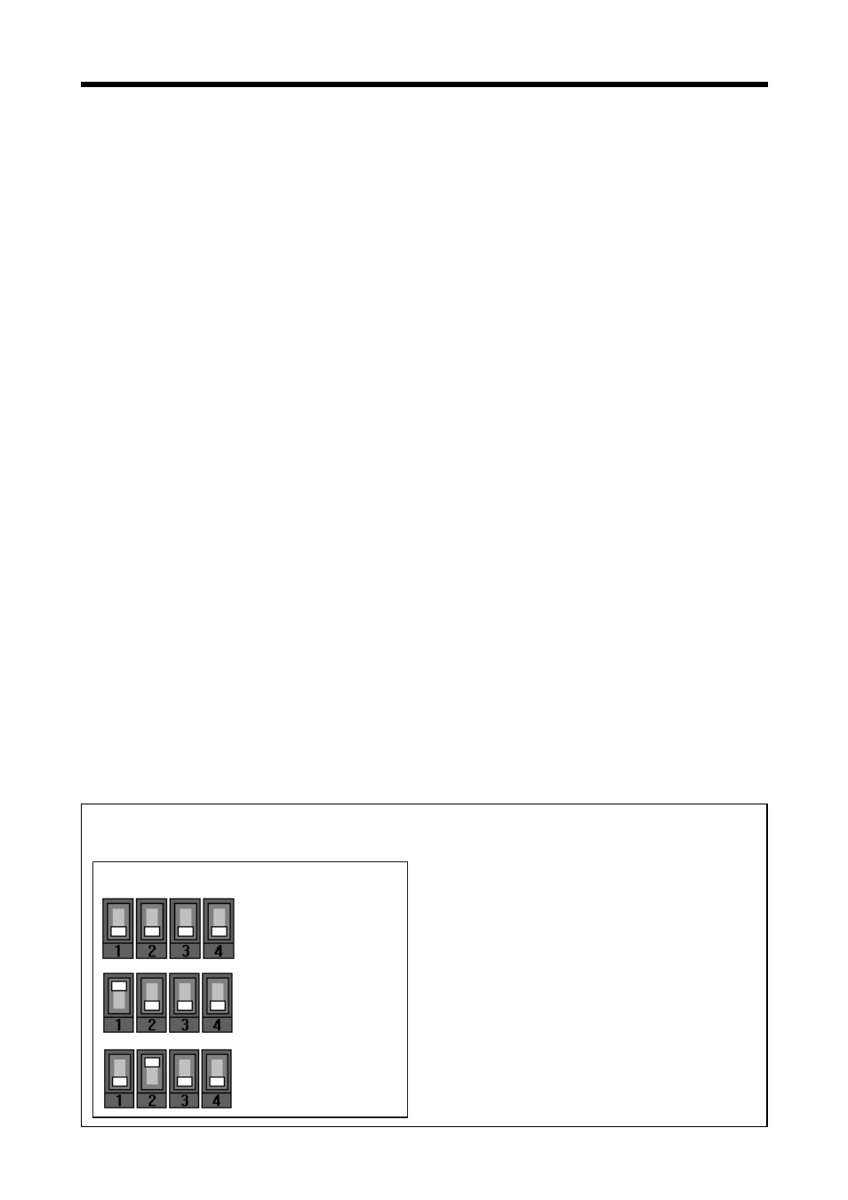
Configuration
DIP-switch settings for:
DICON 400/401/500/501
LOGOPRINT 500
LOGOLINE 500
IMAGO 500
Relay Module 1
IMAGO 500
Relay Module 2
Instructions and DIP-switches on right side of device.
The external module must be
configured with DIP switches
for the device it is connected
to.
Installation
2