Connection diagram – JUMO 902931 Wtrans Receiver with Wireless Data Transmission Data Sheet User Manual
Page 8
2012-06-20/00473257
Data Sheet 902931
Page 8/10
JUMO GmbH & Co. KG
Delivery address: Mackenrodtstraße 14
36039 Fulda, Germany
Postal address:
36035 Fulda, Germany
Phone:
+49 661 6003-0
Fax:
+49 661 6003-607
E-mail:
Internet:
www.jumo.net
JUMO Instrument Co. Ltd.
JUMO House
Temple Bank, Riverway
Harlow, Essex CM20 2DY, UK
Phone: +44 1279 635533
Fax:
+44 1279 635262
E-mail:
Internet: www.jumo.co.uk
JUMO Process Control, Inc.
8 Technology Boulevard
Canastota, NY 13032, USA
Phone: 315-697-5866
1-800-554-JUMO
Fax:
315-697-5867
E-mail:
Internet: www.jumousa.com
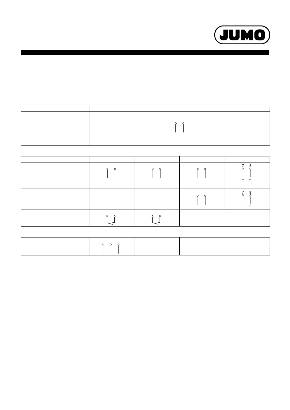
Connection diagram
The connection diagram in the data sheet provides preliminary information about the connection possibilities. Only use the installation instruc-
tions or the operating manual for the electrical connection. The knowledge and the correct technical execution of the safety information/instruc-
tions contained in these documents are mandatory for installation, electrical connection, and commissioning/start-up as well as for safety during
operation.
Voltage supply
Connection for
Terminal assignment
Voltage supply
according to nameplate:
L1 and N at AC 110 to 240 V
L+ and L- at AC/DC 20 to 30 V
Outputs
Basic type 902931/10
Analog output 1
Analog output 2
Analog output 3
Analog output 4
Current 0(4) to 20 mA
or voltage 0 to 10 V
Basic type 902931/30
Relay output 1
Relay output 2
Analog output 3
Analog output 4
Current 0(4) to 20 mA
or voltage 0 to 10 V
Relay
N/O contact,
configurable as an N/C
Digital interface
RS485
9 TxD+/RxD+
10 GND
11 TxD-/RxD-
Transmit/receive data +
Ground
Transmit/receive data -
L1
(L+)
N
(L-)
L1
(L+)
N
(L-)
1
2
–
+
3
4
–
+
5
6
–
+
5
6
–
+
2
1
4
3
10
9
11