Operation and configuration, Setup program – JUMO 902931 Wtrans Receiver with Wireless Data Transmission Data Sheet User Manual
Page 5
JUMO GmbH & Co. KG
Delivery address: Mackenrodtstraße 14
36039 Fulda, Germany
Postal address:
36035 Fulda, Germany
Phone:
+49 661 6003-0
Fax:
+49 661 6003-607
E-mail:
Internet:
www.jumo.net
JUMO Instrument Co. Ltd.
JUMO House
Temple Bank, Riverway
Harlow, Essex CM20 2DY, UK
Phone: +44 1279 635533
Fax:
+44 1279 635262
E-mail:
Internet: www.jumo.co.uk
JUMO Process Control, Inc.
8 Technology Boulevard
Canastota, NY 13032, USA
Phone: 315-697-5866
1-800-554-JUMO
Fax:
315-697-5867
E-mail:
Internet: www.jumousa.com
2012-06-20/00473257
Data Sheet 902931
Page 5/10
Operation and configuration
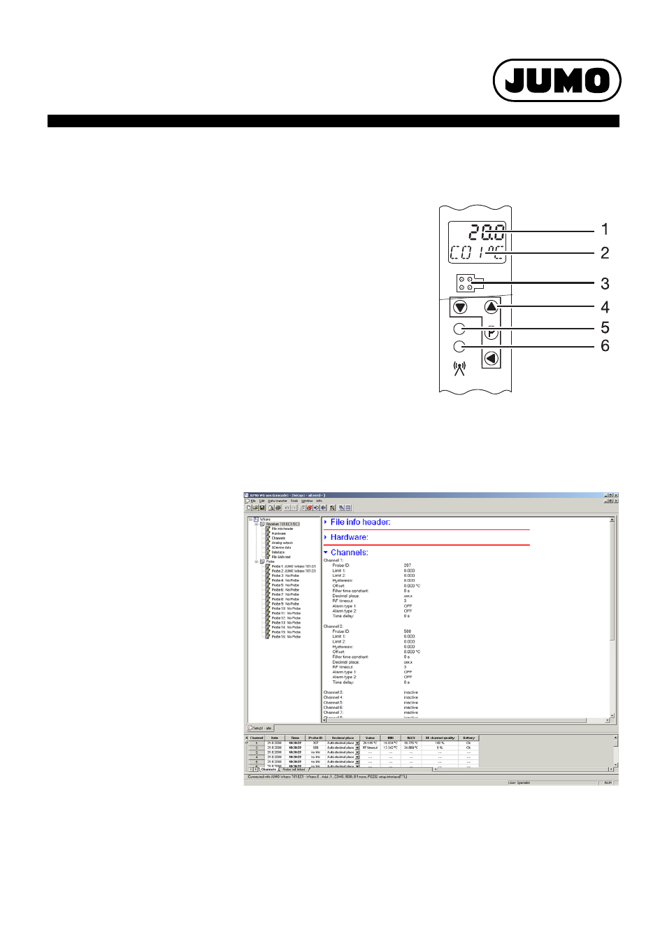
At the receiver
Operation and configuration of the receiver require four keys located at the front. These have
various functions depending on the menu. The dialog is supported by a 2-line LCD display. Two
LEDs signal various operating statuses. The operation and configuration of the parameters are
organized into three different levels:
- Normal display (display of values and signal quality)
- Commissioning/start-up level (channel linking to transmitter ID)
- Parameter level (editing of configuration parameters)
Each of the two levels can be protected against unauthorized access by a code.
1
7 segment LCD display,
4.5 mm, 4 digit
5
Bicolor LED
-
Green = malfunction-free operation
-
Red flashing = collective alarm
(the collective alarm includes the
radio timeout of transmitters 1 to16,
the limit value monitoring min./max.
of channels C01 to C16, detected
memory errors during power on, and
the low battery signal of transmitters
1 to 16)
2
16 segment LCD display,
4.0 mm, 5 digit
3
Setup interface
4
Function keys
6
Yellow short flashing LED
-
Receipt control for each
data packet from the transmitter
Setup program
Configuration via the setup program is more
comfortable than using the receiver keypad.
The configuration data can be archived on
data storage devices and printed.
All configurable parameters are described in
this operating manual.
The setup program can be used to overwrite
changed parameters with the factory settings
at any time.
The connection between receiver and PC is
established via a PC interface (USB/TTL or
TTL/RS232 converter).
OnlineChart (optional)
The OnlineChart extension can graphically
display and save the measured values of eight
analog and four binary channels.
Customer specific linearization
For transmitters with potentiometer or voltage
input the user can define up to four customer-
specific linearizations (value pairs or polyno-
mial formula).