Protective, regulation, and control devices, Safety temperature limiter stb, Connection possibilities of the sensors – JUMO 14597 safetyM STB/STW Ex - Safety Temperature Limiter and Safety Temperature Monitor Data Sheet User Manual
Page 11
Page 11/16
Data Sheet 701155
2012-10-01/00542385
JUMO GmbH & Co. KG
Delivery address: Mackenrodtstraße 14
36039 Fulda, Germany
Postal address:
36035 Fulda, Germany
Phone:
+49 661 6003-0
Fax:
+49 661 6003-607
E-mail:
Internet:
www.jumo.net
JUMO Instrument Co. Ltd.
JUMO House
Temple Bank, Riverway
Harlow, Essex CM20 2DY, UK
Phone: +44 1279 635533
Fax:
+44 1279 635262
E-mail:
Internet: www.jumo.co.uk
JUMO Process Control, Inc.
6733 Myers Road
East Syracuse, NY 13057, USA
Phone: 315-437-5866
1-800-554-5866
Fax:
315-437-5860
E-mail:
Internet: www.jumousa.com
Protective, regulation, and control devices
Safety temperature monitor STW
1
The safety temperature monitor is a device that is automatically reset when activated once the sensor temperature has fallen below or
risen above the set limit value by an amount equal to the switching differential. Possible settings: monitoring for limit value overrange or
underrange.
Mode of operations:
Minimum requirements: 2B, 2K, 2P
Additional requirements: 2N, 2D
Safety temperature limiter STB
1
The safety temperature limiter is a device that is permanently locked after responding.
Manual reset using the RESET key is possible once the probe temperature has fallen below / has exceeded the limit value by the
amount of the switching differential. Possible settings: monitoring for overrange or underrange.
Mode of operations:
Minimum requirements: 2B, 2J, 2V, 2K, 2P and adjustable with special tools
Additional requirements: 2N, 2F, 2D
1.
For more detailed explanation, see DIN EN 14 597.
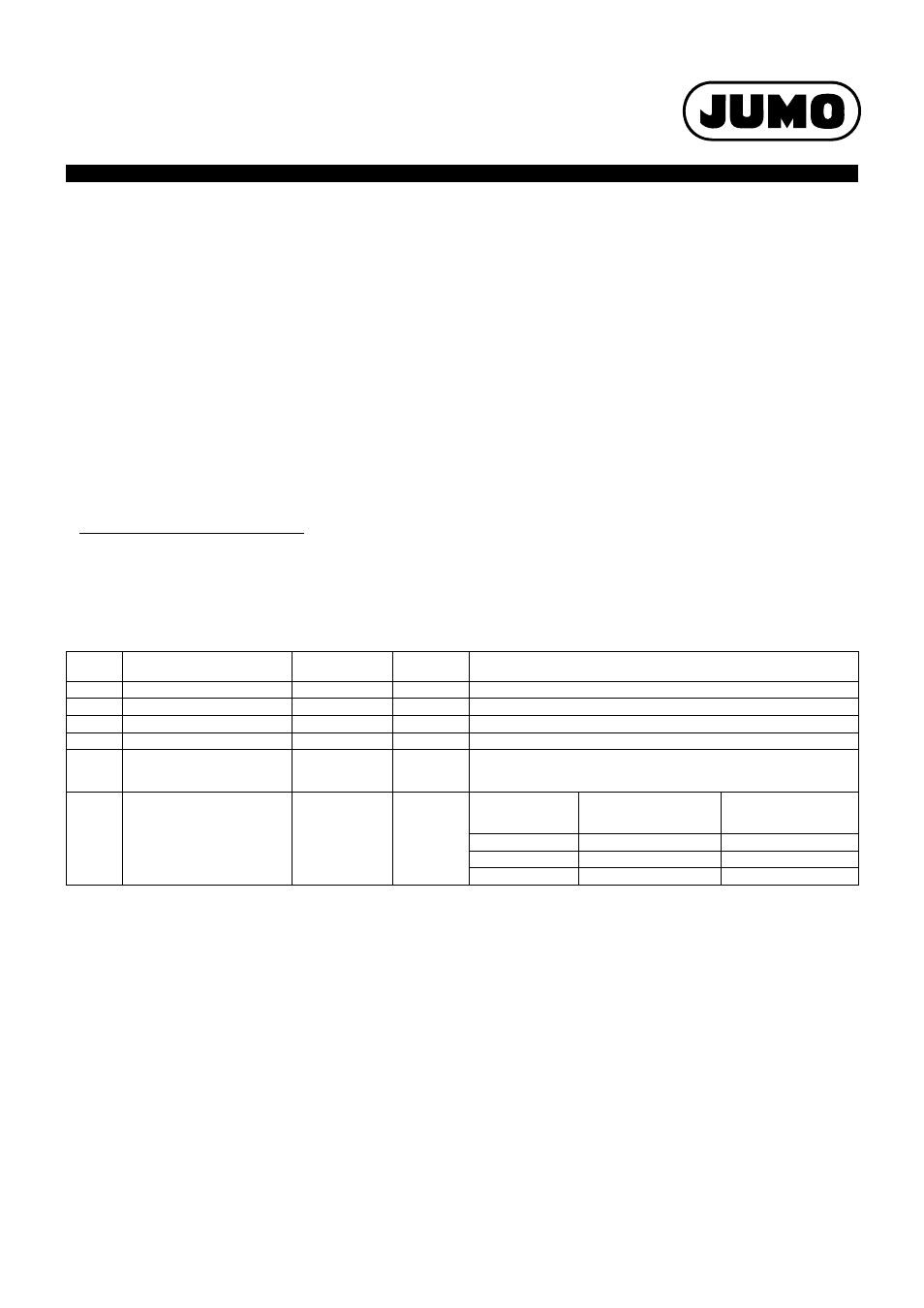
Connection possibilities of the sensors
The JUMO safetyM STB/STW evaluation device structure is basically identical. Various possibilities to connect the sensors are available. These
possibilities are listed in the following table along with the achievable SIL level:
Important information:
Variants 1 to 4 were evaluated with JUMO probes according to data sheets 901006 and 902006. For variant 5 no sensor system was included.
In this case, the user selects the sensor system. For this reason, the user is responsible for evaluating the achievable SIL.
If the used SIL-capable sensor consists of hardware and software (e.g. transmitter), the maximum SIL that can be achieved – irrespective of the
architecture – is the one according to which the sensor software was developed (so, for example, if the sensor software has SIL2, the max. achiev-
able SIL is 2).
The possibility to connect passive sensors such as double thermocouples or Pt100/1000 sensors means that the sensors do not necessarily
require a SIL qualification. In this case, the specification of the failure rates for the passive sensors is sufficient for the SIL qualification of the
overall system. The user of the system must always determine the PFD
avg
and/or PFH value of the overall safety chain to evaluate the achieved
SIL.
Variant
Connected sensors
Sensor system ar-
chitecture
Logic archi-
tecture
Achievable SIL
1
1x Pt100 2-wire circuit
1oo1
1oo2D
SIL2
1a
2x Pt100/1000 2-wire circuit
1oo2
1oo2D
SIL3
2
2x Pt100/1000 3-wire circuit
1oo2
1oo2D
SIL3
3
2x thermocouple
1oo2
1oo2D
SIL3
4
1x Pt100/1000 2-wire and 3-wire
circuit
1x thermocouple
1oo2
1oo2D
SIL3
5
STB/STW 701155 without sensor
system 1oo2D architecture.
No probe or use of the input 4 to
20 mA
(means that the sensor is not tak-
en into account for the calcula-
tion).
Sensors connected
by the system user
architecture acc. to
connection 1oo1 or
1oo2
1oo2D
SIL of the used sen-
sor (HW only)
Max. achievable SIL of the
system with 1oo1 sensor
system architecture
Max. achievable SIL of the
system with 1oo2 sensor
system architecture
SIL1
SIL1
SIL2
SIL2
SIL2
SIL3
SIL3
SIL3
SIL3