Connection diagram – JUMO 14597 safetyM TB/TW08 Temperature Limiter and Temperature Monitor Data Sheet User Manual
Page 7
2012-07-01/00524703
Data sheet 70.1170
JUMO GmbH & Co. KG • 36035 Fulda, Germany
Page 7/10
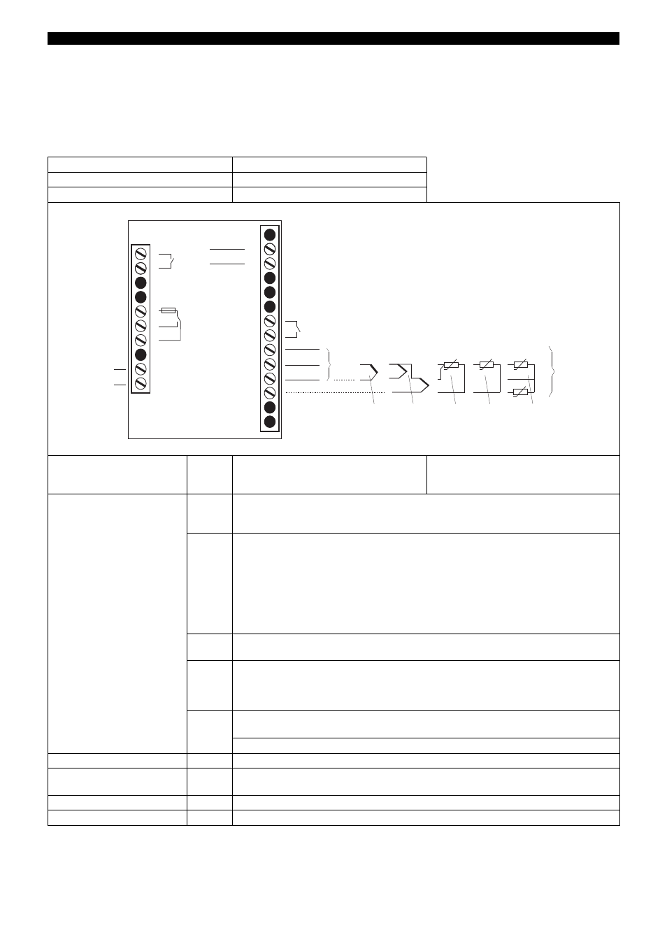
Connection diagram
The connection diagram contained in the data sheet provides preliminary information about the connection possibilities. Only use the
installation instructions or the operating manual for the electrical connection. The knowledge and the correct technical execution of the
safety information/ instructions contained in these documents are prerequisite for installation, electrical connection and commissioning/
start-up as well as for safety during operation.
Lead
Admissible cross section
1 wire
≤
2.5 mm
2
fine-strand, with core-end ferrule
≤
1.5 mm
2
Connection via plug-in terminal strips.
Voltage supply
as per rating plate
(8)
AC
L1 Line conductor
N Neutral
DC
(L+)
(L-)
Analog inputs
(6.2)
(6.3)
Thermocouple/
Double thermocouple
(safety tested)
(6.5)
RTD temperature probe in 2-wire circuit
(safety tested)
or KTY11-6 PTC in 2-wire circuit
(6.4)
RTD temperature probe in 3-wire circuit
(safety tested)
(6.6)
RTD temperature probe 2 x Pt100 in
2-wire circuit for differential value calculation (no lead compensation possible)
INP (terminal 22 and 21)
IN2 (terminal 21 and 20)
(6.1)
0... 20 mA
(4) ... 20 mA (safety tested)
0(2) ... 10 V
Binary input
(5.1)
for connection to potential-free contact
Analog output
(extra code)
(4)
configurable:
0... 20 mA, (4) ... 20 mA (ex-factory), 0 ... 10 V or 0(2) ... 10 V
Relay output KV
(1)
Relay (N/O) without shroud
Relay output K1
(2)
Relay (change-over contact element) with fuse cut-out
1
2
5
6
N(L-)
L1(L+)
12
15
16
17
20
21
22
23
AC/
DC
19
18
24
(1)
(2)
(8)
(5.1)
+
-
0/4...20mA
-
+
J
J
0/2...10V
+
(6)
(6.1)
(6.2)
(6.3)
(6.5)
0/4...20mA
0/2...10V
+
-
(4)
13
+
+
-
(6.4)
J
J
(6.6)
7
14
11
3
4
8
A
Enter the lead resistance for RTD temperature probes in 2-wire circuit when using
greater line lengths.
Setup program:
edit
extended configuration