Valid range – JUMO 14597 safetyM TB/TW08 Temperature Limiter and Temperature Monitor Data Sheet User Manual
Page 5
2012-07-01/00524703
Data sheet 70.1170
JUMO GmbH & Co. KG • 36035 Fulda, Germany
Page 5/10
Switching behavior with differential value as absolute value
Test voltages as per EN 60730, part 1
Electrical safety
Environmental influences
Housing
Input and output against voltage supply
- at a voltage supply AC 110 ... 240V +10% /-15%
3.7kV/50Hz
- at a voltage supply AC/DC 20 ... 30V, 48...63 Hz
3.7kV/50Hz
Clearances and creep paths
Mains to electronic components and probe
≥
6 mm
/ ≥
8 mm
Mains to the relay
≥
6 mm
/ ≥
8 mm
Relay to electronic components and probe
≥
6 mm
/ ≥
8 mm
Relay to Relay
≥
6 mm
/ ≥
8 mm
Electrical safety
accord. to DIN EN 14597 (DIN EN 60730-2-9) Overvoltage category III, pollution degree 2
Protection type I
with internal separation to SELV current circuits
Ambient temperature range
0 ... +55°C
Storage temperature range
-30 ... +70°C
Temperature coefficient
≤
± 0.005% / K dev. from 23°C
1
for RTD temperature probes
≤
± 0.01% / K dev. from 23°C
1
for thermocouples, current, voltage
Ambient conditions
85% rel. humidity without condensation
(3K3 with extended temperature range as per DIN EN 60721-3-3)
EMC
according to DIN EN 14597 and standards from the standard series DIN EN 61326
Interference emission
Class B
Interference immunity
Test level for protective, regulation and control devices (RS) as per DIN EN 14597
1 All specifications referring to the measuring range limit value
Material
Polycarbonate
Flammability class
UL 94 V0
Electrical connection
via plug-type screw-in terminals up to max. 2.5 mm
2
Installation
Panel mounting as per DIN IEC 61554
Installation position
vertical
Weight
approx. 175g
Protection type
as per DIN EN 60529, at the front IP 65, at the rear IP 20, degree of soiling 2
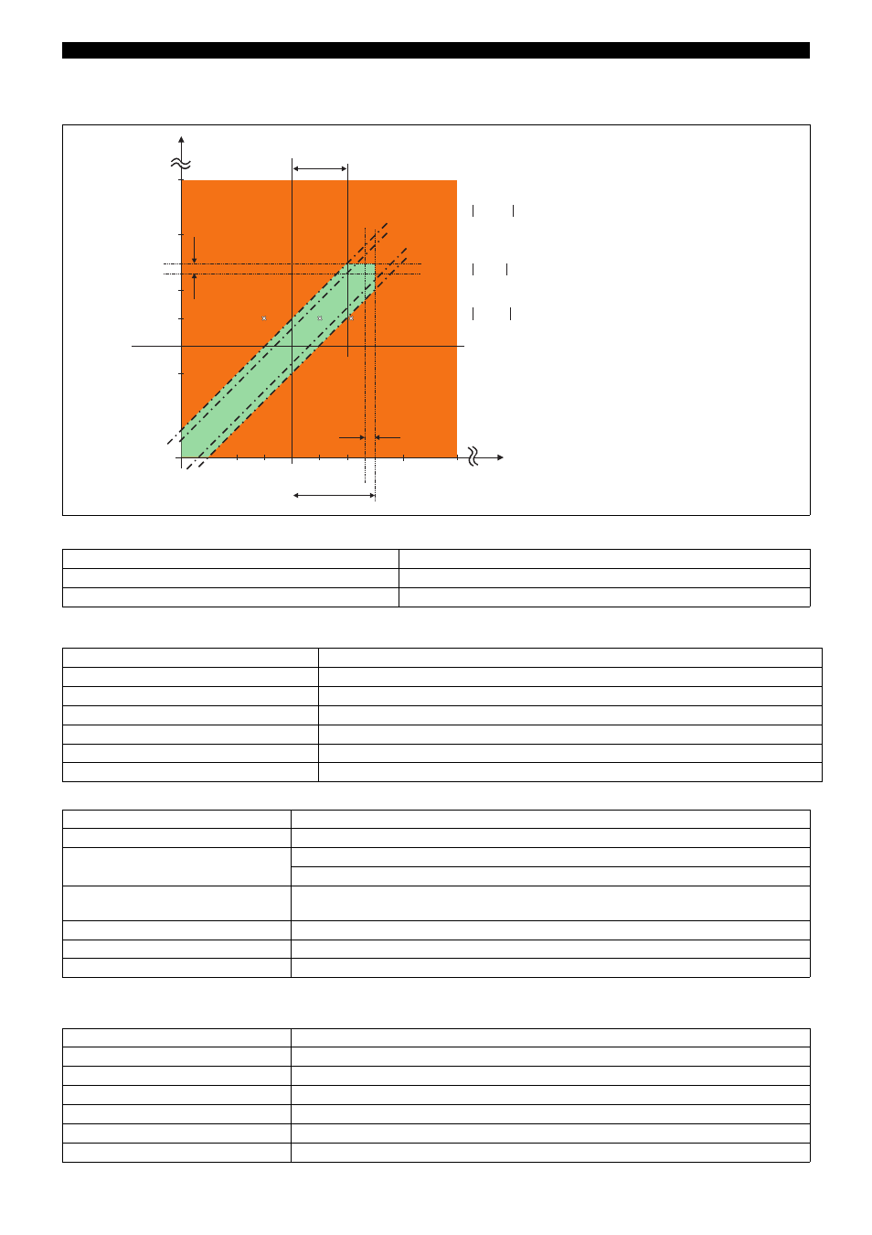
-200°C
300°C
AL = 150°C (inverse)
0°C
200°C
100°C
-100°C
300°C
200°C
100°C
0°C
-100°C
-200°C
Ald = 50°C
IN2
INP
valid range
Hys1
Hys1
All difference values
range (green)
are smaller than the
setting for
valid range
and lies inside the valid range
exceeds
and lies
out of the valid range
The area between the dot and dash lines indicate
the span of the hysteresis (factory setting: 1K)
The inputs INP and IN2 are additionally monitored
in regards to the limit value AL=150°C
Example
Example
diF = INP-IN2 are shown in the picture.
Inside the valid
all values
the difference ALd = 50.
INP = 101°C,
101 - 50 = 51 exceeds Ald = 50 and lies out of the
.
Example 1:
IN2 = 50°C
INP = 50°C, IN2 = 50°C
50 - 50 = 0
.
INP = -50°C, IN2 = 50°C
-50 - 50 = 100
Ald = 50
.
2:
3:
50°C
1
2
3
-50°C