Wiring diagrams – JUMO 603021 Surface-Single Mounted Thermostat, ATH series Data Sheet User Manual
Page 4
Data Sheet 603021
JUMO GmbH & Co. KG
Delivery address: Mackenrodtstraße 14
36039 Fulda, Germany
Postal address:
36035 Fulda, Germany
Phone:
+49 661 6003-0
Fax:
+49 661 6003-607
E-mail:
Internet:
www.jumo.net
JUMO Instrument Co. Ltd.
JUMO House
Temple Bank, Riverway
Harlow, Essex CM20 2DY, UK
Phone: +44 1279 635533
Fax:
+44 1279 635262
E-mail:
Internet: www.jumo.co.uk
JUMO Process Control, Inc.
6733 Myers Road
East Syracuse, NY 13057, USA
Phone: 315-437-5866
1-800-554-5866
Fax:
315-437-5860
E-mail:
Internet: www.jumousa.com
2014-01-08/00073225
Page 4/10
Case
Process connection*
* For different process connections and thermowells refer to data sheet 606710.
Note:
Physical and toxicological properties of the expansion medium that could escape in the event of a measuring system break.
1
At present, no statement concerning health hazards in the event of short-term exposure and low concentration
(e.g. measuring system rupture) has been made by the health authority
Standard
Case lid: polycarbonate, shock resistant
Case bottom section: aluminum die casting, painted
Color: pebble gray RAL 7032
Color: anthracite gray RAL 7015
Extra code "701"
Case lid made of aluminum die casting, painted
Color: pebble gray RAL 7032
Setpoint value
adjustment
ATH-1:
Switching point can be adjusted externally
with the rotary knob
ATH-2, ATH-20, ATH-70
Switching point can be adjusted with a screwdriver
once the case lid has been removed
Protection type
Design 1 + 2:
Design 9 (hazard detector):
EN 60529-IP54
EN 60529-IP44
Cable inlet
Standard: self-sealing grommet M20 × 1.5, sealing range 8 to 10 mm
Weight
Approx. 0.5 kg
Switching head
mounting
ATHf- . series
with capillary
Standard
Screw connection with counter nut M18 × 1 on the case spigot,
capillary exit on the case spigot
Extra code
711
With 2 screws through the case bottom section, lateral capillary exit on the case,
lid and bottom part made of plastic
764
Mounting flange made of steel sheet, capillary exit on the case spigot
248
Wall mount
Series
ATHs-
with rigid thermowell
Scale limit value up to 150 °C
Thermowell "20"
Scale limit value exceeding 150 °C
Thermowell "30"
Screw-in sleeve with screw-in spigot G 1/2
form A according to DIN 3852/2
Screw-in sleeve with screw-in spigot G 1/2
form A according to DIN 3852/2
and intermediate piece,
to ensure that the max. admissible ambient temperature
of +80 °C is not exceeded on the case
Type
ATHf-
With capillary
Plain cylindrical probe "10" (standard)
Screw-in thermowell "20" (upon request)
Screw-in sleeve with screw-in spigot G 1/2 form A acc. to DIN 3852/2
and clamping piece with fixing screw to lock the probe in place
Material
Thermowell "20"
Thermowell "30"
Up to +150 °C CuZn as standard
over +150 °C CrNi
Above +150 °C CrNi
Insertion length S
Standard lengths: 100, 120, 150, 200, or 300 mm
different lengths upon request
Immersion tube Ø
D = 8 mm, D = 10 mm
Control range
with scale limit value
Hazardous re-
actions
Fire and explosion hazard
Hazardous
to waters
Toxicological data
Ignition
temperature
Explosion limit
Irritant
Dangerous to
health
Toxic
<
+200 °C
No
+ 355 °C
0.6 to 8 V%
Yes
Yes
1
No
≥
200 °C
≤ +350 °C
No
+ 490 °C
- -
Yes
Yes
1
No
> 350 °C ≤ +500 °C
No
No
No
No
No
No
No
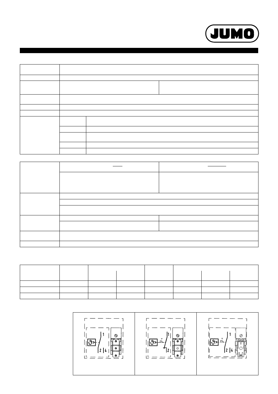
Wiring
diagrams
ATH.-1
ATH.-2
ATH.-20
ATH.-70
ATH.-70/574